Whistle

a technology of whistle and resonance chamber, which is applied in the field of whistle, can solve the problems of poor design, shrill and unpleasant sounds, and the size of the resonance chamber cannot meet the need for a small and lightweight whistle, and achieve the effect of suppressing the hardness of hearing or ringing of the ears of whistle-blowers, reducing the resonance frequency and reducing the size of the resonance chamber

Inactive Publication Date: 2009-11-05
SHISHIDO HIDEOMI
View PDF12 Cites 5 Cited by
  • Summary
  • Abstract
  • Description
  • Claims
  • Application Information

AI Technical Summary

Benefits of technology

[0023]According to this whistle, resonant sound waves are generated in both the first resonance chamber and the second resonance chamber. Further, resonant sound waves are generated in a connected resonance chamber that comprises the first resonance chamber and the second resonance chamber. The wa

Problems solved by technology

Sounds at these frequencies, and sounds having harmonics based on these frequencies, are shrill and unpleasant sounds, and so improvement has been sought.
However, merely increasing the size of the resonance chamber fails to satisfy the need for a small and lightweight whistle, and is poor in terms of design as well.
Moreover, the whistles of the prior art give rise to the following problem.
As a result, in the case of the whistles of the prior art the whistle-blower must listen to the sound at high volume, normally approximately 120 dB/m, and at an unpleasant high frequency.
This entails the possibility of affliction of the whistle-blower with a hearing disorder, or of ringing of the ears, or other problems.
Even when such problems do not occur, sports referees and similar who blow whistles for extended periods of time may then not be able to hear sounds for some time thereafter.
However, due to the circular shape of the side faces of the cylindrical body, the grasping angle is not readily determined.
Further, the area to hold the whistle is insufficient.
Hence there are problems such as failure of the whistle-blower to hold the whistle, or delays in blowing the whistle.
The pealess-type whistle 604 also has a side face height which is only approximately half the size of the fingertips of an adult, and so has the problem of being extremely hard to hold.
If the overall dimensions are made large, the above problem can be resolved, but this fails to meet the need for a

Method used


Image

  • Whistle
  • Whistle
  • Whistle

Examples


first embodiment

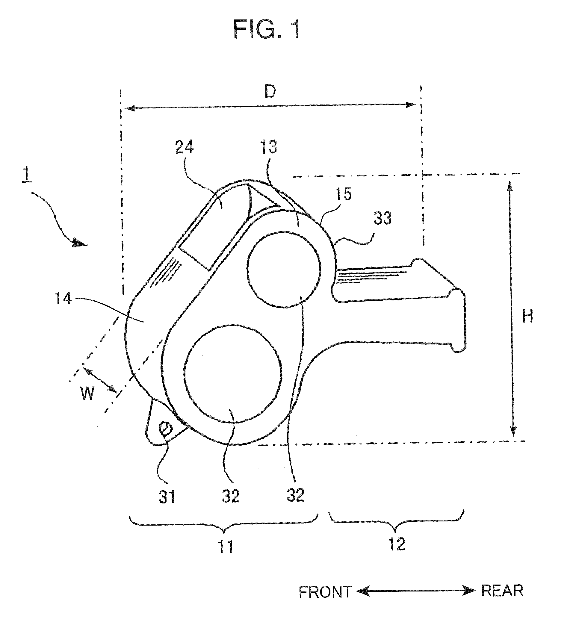
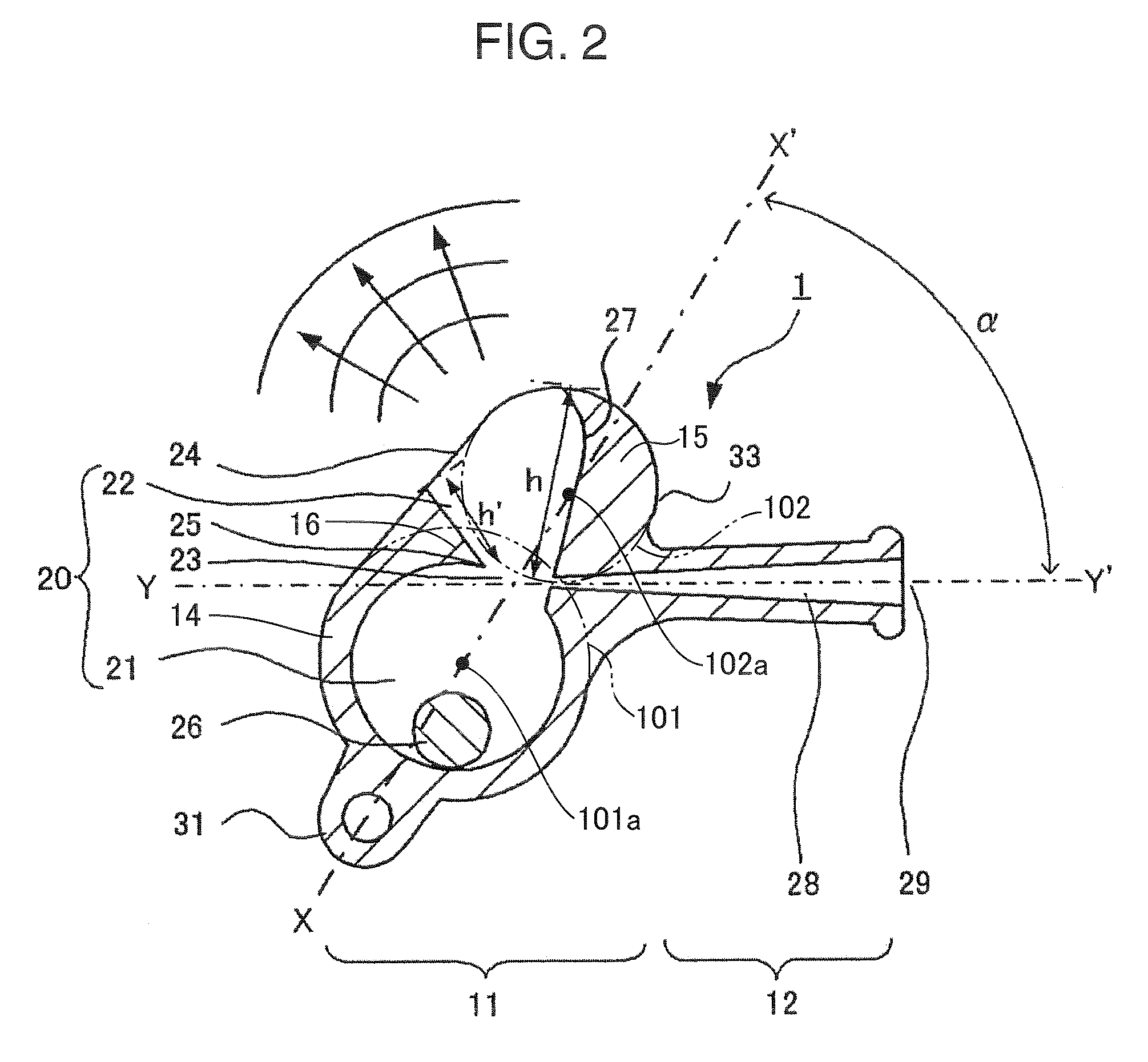
[0038]The whistle 1 of a first embodiment of the invention is explained, referring to FIG. 1 and FIG. 2. The whistle 1 is a so-called pea-type whistle. FIG. 1 is a perspective view showing the external appearance of the whistle 1. FIG. 2 is a cross-sectional view of the whistle 1.

[0039]The whistle 1 comprises a body portion 11 and a mouthpiece portion 12.

[0040]The body portion 11 has a vertically long and narrow shape. This body portion 11 has a connected resonance chamber 20. The body portion 11 has right and left side plates 13, extending in the vertical direction and forming the connected resonance chamber 20; a front wall 14, extending horizontally on the front side between these side plates; and a rear wall 15, extending horizontally between these side plates. The connected resonance chamber 20 comprises a first resonance chamber 21, a second resonance chamber 22, and an orifice 23. The front face, that is, the outside face of the front wall 14 of the body portion 11 is incline...

second embodiment

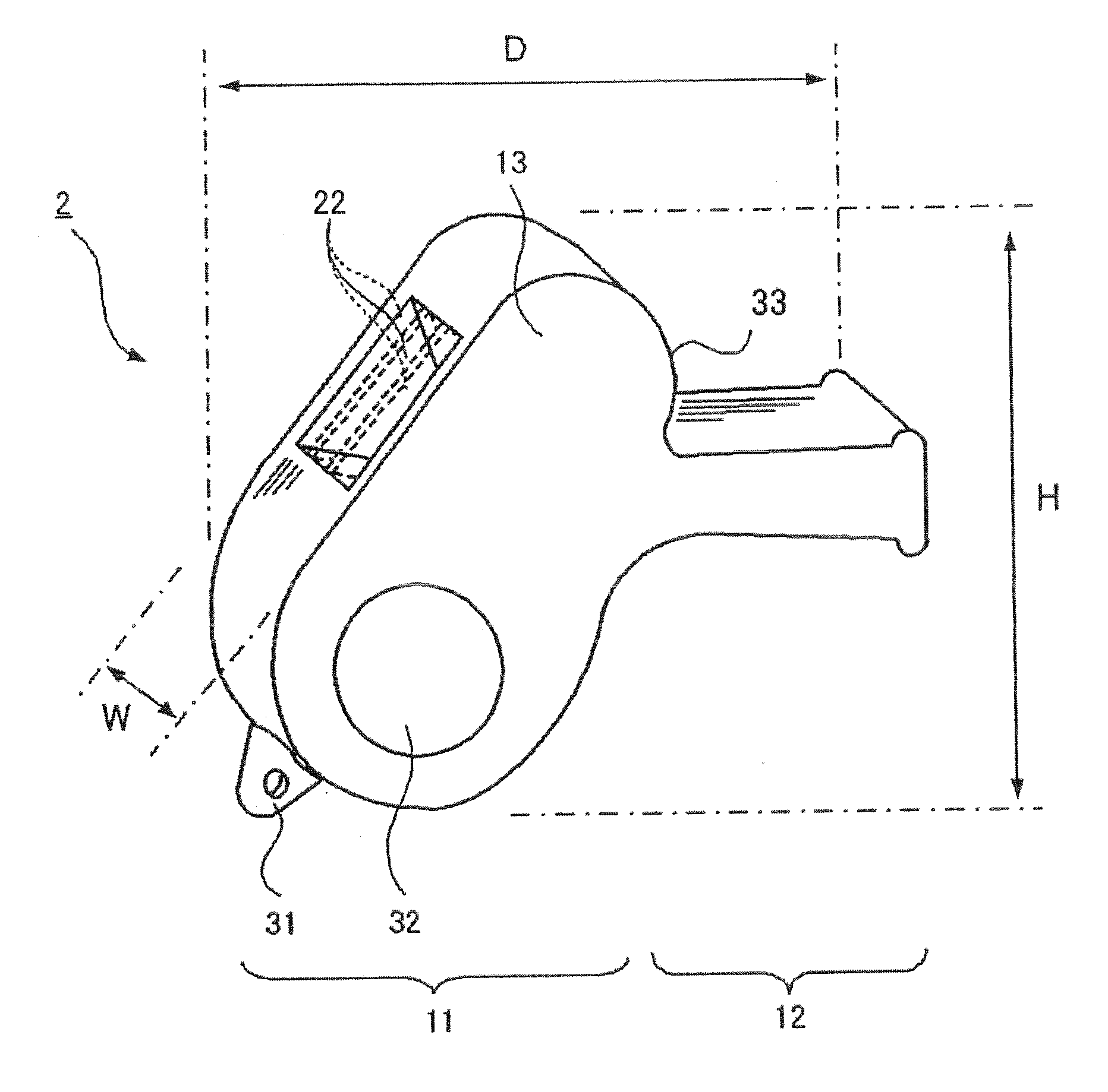
[0077]The whistle 2 of a second embodiment is explained, referring to FIG. 4 and FIG. 5. FIG. 4 is a perspective view showing the external appearance of the whistle 2, and FIG. 5 is a cross-sectional view of the whistle 2. The whistle 2 is a so-called pealess-type whistle.

[0078]Similarly to the resonance chamber of an ordinary pealess-type whistle, the first resonance chamber 21 is a rectangular parallelepiped-shape space. However, the first resonance chamber 21 of the whistle 2 of the second embodiment is inclined forward and downward.

[0079]The second resonance chamber 22 widens toward the sound-emitting opening 24, and the sound-emitting opening 24 opens in the front face of the body portion 11 formed forward and downward, and directs forward and upward. The air passageway 28 is flexed downward midway, and the front end of this air passageway 28 opens forward and slightly downward. The angle β made by the axis X-X′ of the body portion 11 and the axis Y-Y′ of the mouthpiece portion...

embodiment 1

[0083]A pea-type whistle 1 of the above first embodiment, and as a reference example a whistle the same size as this but with the second resonance chamber removed, that is, similar to the whistle 503 shown in FIG. 9A, were fabricated, and the frequency characteristics of each were measured. And, examination to determine whether there was a shift to the low-frequency side of sound waves of the whistle 1 of the first embodiment was performed. Also, an examination was performed to determine whether the resonance sound was increased and the sound had more richness. The heights of the second resonance chamber of the whistle of the first embodiment used in measurements were h=14 mm and h′=10 mm.

[0084]A sound-level meter was installed at a position 1 m forward from each of the whistles in an anechoic chamber. Compressed air corresponding to human exhalation was supplied to the air opening from a compressor, and differences in sound quality due to the presence or absence of the second reson...


PUM


Abstract

An object of the present invention is to provide a whistle which has a resonance frequency shifted to the low-frequency side and a pleasant tone while retaining a compact size and light weight. In order to attain this object, a whistle comprises a mouthpiece portion, inside which an air passageway is formed and in which an air opening is opened, and a body portion, in which a connected resonance chamber that is connected to the air passageway is formed; the connected resonance chamber comprises a first resonance chamber, a second resonance chamber in which a sound-emitting opening is opened, and an orifice connecting the first resonance chamber and the second resonance chamber.

Description

BACKGROUND OF THE INVENTION[0001]1. Field of the Invention[0002]This invention relates to a whistle.[0003]2. Description of the Related Art[0004]Whistles are widely used by referees in various sporting events, for policing, guidance, and signaling where many people are gathered, as well as for guiding or training pets, and in numerous other fields as a simple tool for audio communication. A whistle must promptly convey sound to persons and animals in the environs, according to the various environments of use, and must excite their attention. For these reasons, a whistle-blower requires a whistle which can easily be held so as to enable prompt blowing as necessary. Moreover, listeners require a whistle emitting a sound with an easily discernible pitch and volume that can immediately be recognized. Whistles currently in use include pea-type whistles, having a pea which rotates within a resonance chamber, and pealess-type whistles, which have no pea. FIG. 9A shows a pea-type whistle 50...

Claims


Application Information

Patent Timeline
IPC IPC(8): G10K5/00
CPCG10K5/00
Inventor SHISHIDO, HIDEOMI
Owner SHISHIDO HIDEOMI
Why Eureka
Try Eureka