Particulate detector

a technology of particle detection and detector, applied in the field of particle detection, can solve the problems of reducing the performance of the turbine, faulty components, and inability to detect the results of contaminated areas, and achieve the effects of easy control, low back scatter or sparkle, and intense sparkl

Inactive Publication Date: 2007-07-31
POLLUTION CONTROL & MEASUREMENT EURO
View PDF9 Cites 17 Cited by
  • Summary
  • Abstract
  • Description
  • Claims
  • Application Information

AI Technical Summary

Benefits of technology

[0015]The apparatus and method of the present invention rely on the detection of sparkle from particulate of illumination to which they are subjected. By the term “sparkle” is meant glitter or glisten of illumination from a particulate. The sparkle may be in any direction as illumination is reflected from the particulate; at least some of the sparkle will be in the direction of the detector. In an area of gas flow, the apparatus of the invention, and its method, enable more accurate determination of particulate suspended in the gas flow over substantially the whole cross section of the duct. If gas close to the outlet of a filter is essentially laminar, it is preferred that the apparatus of the invention is located in the area of laminar flow. Such positioning will enable more precise determination of the location of a fault in a particular filter in a planar array of filters.
[0016]The apparatus of the invention will be located within an inlet or outlet duct which directs gas into or out from a location. The duct may be constructed from any suitable material known in the art. Examples of ducting include metal, typically, steel which may be coated or uncoated (e.g. galvanised), stainless steel, aluminium; plastics materials, for example rigid or flexible polyvinyl chloride, polypropylene, polystyrene, low or high density polyethylene, ABS and the like; and the ducting may be in concertina form. The ducting may be of any convenient or suitable cross section such as, for example, rectangular (e.g. square), circular, oval, and have any cross sectional size provided that the cross section can accommodate the emitter and detector. The emitter and / or the detector may be located within the cross section of the ducting; however, where there is very high throughput of gas, the emitter and the detector are preferably located in the wall of the ducting or adjacent a window (transparent to the illumination) in the ducting wall so that the emitter or detector do not reduce throughput of gas and the risk of any part of the emitter or detector being dislodged and damaging the duct or apparatus is reduced.
[0018]Infra red illumination, which has lower costs than other emitters described below may be used and whilst any water vapour present in the duct or gas will absorb at least some of the infra red illumination, such disadvantage may be alleviated by use of detectors such as, for example CCD cameras (which have a peak sensitivity at about 675 nm) which are sensitive in an area of low absorption in the infra-red spectrum of water; however illumination intensity is comparatively low (which may be compensated for by increasing sensitivity of detectors) and poor collimation and longer wavelength may limit detectability of sparkle.
[0020]Microwave illumination is not a suitable source of radiation because vibrations in the duct and external movements to the duct cause vibrations which render any detection of sparkle unreliable. Also commercially available microwave systems rely on Doppler Shift for detection of particulates which is a different effect from that required in the present invention; Doppler Shift measures speed of particles and hence microwave systems provide little back scatter or sparkle. Furthermore, the wavelength of microwave illumination is very large compared to the normal dimensions of individual particulate particles, bulk reflection of microwave illumination occurs from clouds of particulate. Beam size and direction are relatively easily controllable and so give adequate control of coverage of the duct, but multipathing is a problem associated with microwave radiation. Also transparency of materials from which the duct is made can result in unwanted signals.
[0021]Illumination in the visible spectrum is preferred. Illumination having wavelength from 460 nm to 680 nm is preferred. Emitters of visible illumination include that, for example, from a filament lamp, light emitting diode, but such light generally may not have adequate intensity or be capable of being focussed to provide a beam having required collimated beam. A much preferred emitter is a laser. It has been found that lasers produce intense sparkle from particulate and laser devices have comparatively longer operating life. Suitable lasers have output of at least 1 mW, and output may be determined having regard to particulate size and required sensitivity of the apparatus. Matching of a single frequency emitter with a detector specific for that frequency results in greater signal to noise ratio in detection and hence greater sensitivity of the apparatus of the invention. The duct may be provided with a beam dump to absorb illumination, in particular illumination from a laser, on the side of the duct opposite to the emitter so that illumination is not reflected back from the opposite side of the duct. A band pass filter may also be provided to reduce any effect of non-emitter emitted illumination.
[0023]Fanning of the beam from the emitter by means of, for example, a optical lens, preferably cylindrical, converts a narrow beam into a fan having any desired inclusive angle, preferably about 90°. Such fanning has advantages of low cost, no moving parts and hence requiring little setting-up or alignment; however the intensity of the illumination diminishes rapidly as distance from the emitter increases due to large (and deliberate) divergence of the beam, power is spread over a large area so that emitter output increase is required for any given detector sensitivity, and a 2-dimensional detector is required to monitor sparkles occurring within the whole of the fan. Mechanical scanning of the beam from the emitter by means of, for example, a lens or an essentially continuous mechanically moved mirror enables the beam to be swept through a desired scan angle. Typically a mirror is controlled with a servo galvanometer or a stepper motor, the latter being preferred where mechanical robustness of the apparatus is required; an additional advantage of a stepper motor is that information relating to the position of the emitter beam can be used to mask out any spurious signal. The advantages of such a system enable a constant intensity along the length of the beam (excluding any absorption), maintain high intensity i.e. little spreading of the beam other than normal divergence, and scanning parameters such as sweep angle and sweep rate can be easily controlled. The sweep duration may be from tens of sweeps per second to a few minutes; longer sweep times allow for very sensitive detection of small particulate trails, and small sparkles detection can be integrated over a period of seconds to facilitate measurements of particulate of greater reliability and reproducibility; faster sweep rates generally allow quicker remedial action in the event of catastrophic abatement system failure.

Problems solved by technology

The presence of particulate is in many situations at least a nuisance and at worst catastrophic or illegal.
Particulate can carry impurities into locations where its presence is undesirable.
Thus in the manufacture for example of electronic components the presence of particulate can lead to impurities being included inadvertently in the component, for example, a chip, so rendering the component faulty.
Many testing procedures are carried out in areas which are intended to be sterile and particulate free; the presence of particulate may lead to test results from such contaminated areas worthless.
In electricity generating stations, for example, particulate in the inlets to turbines must be kept to a minimum in order to reduce particulate build up on the turbine blades; such build up has to be removed, generally by water spraying, or, if not carried out, leads to a reduction in turbine performance and ultimately blade disintegration with obvious destructive results.
Such a practice is environmentally unacceptable and particulate emissions must be kept within approved maximum or legal limits.
It is also found however that an abatement system may fail catastrophically before that period has been exhausted and allow unacceptable passage of particulate through the filter system.
This is a particular problem where, for example, the gas flow is very high or where the abatement system comprises a set of filters and one filter in the set should prematurely fail.
Furthermore, such a detector does not provide monitoring of low levels of particulate.

Method used


Image

  • Particulate detector
  • Particulate detector
  • Particulate detector

Examples


example 1

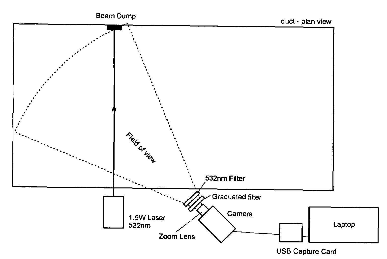
[0032]FIG. 1 is a plan view of an apparatus according to the invention is shown diagrammatically in which illumination is provided from an emitter 2 which is a laser having output 1.5 W, a beam width of about 2 mm, at a wavelength of 532 nm (green). The beam is fanned, using a cylindrical lens, across a duct 4 from one wall at approximately right angles to the beam wall, 50% of the cross section of the duct being illuminated. At the opposite wall, a beam dump 6 is provided to absorb illumination received at that point so that essentially no emitted light is reflected back from that wall. Sparkles from any particulate in the duct are detected by a 0.08 Lux C / CS mount CCD camera 8 having a 12 mm lens having the centre of its field of view about at an angle of 45° across the duct. The camera is fitted with a zoom lens 10 to focus the field of view, and with a 532 nm filter 12 so as to accept only sparkles caused by light from the emitter, and with a graduated neutral density filter 14 ...

example 2

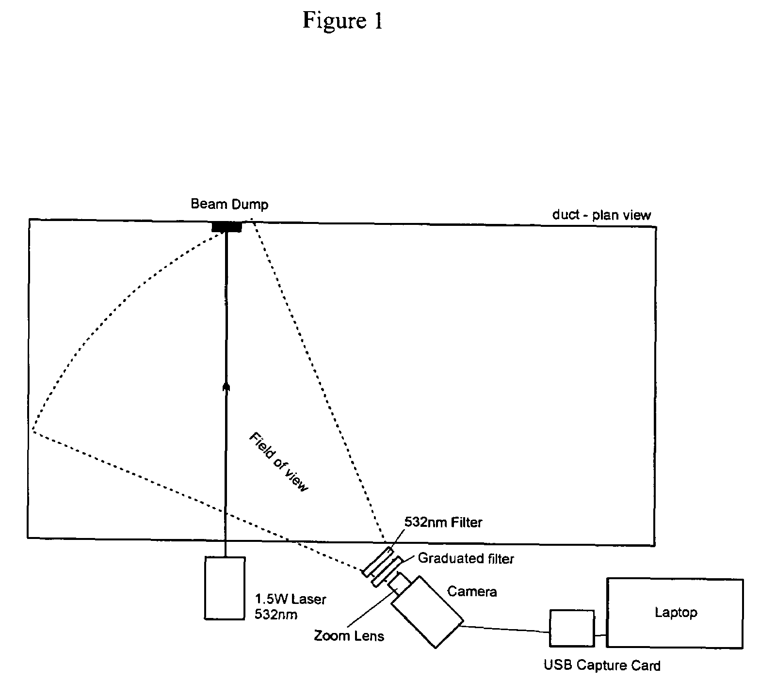
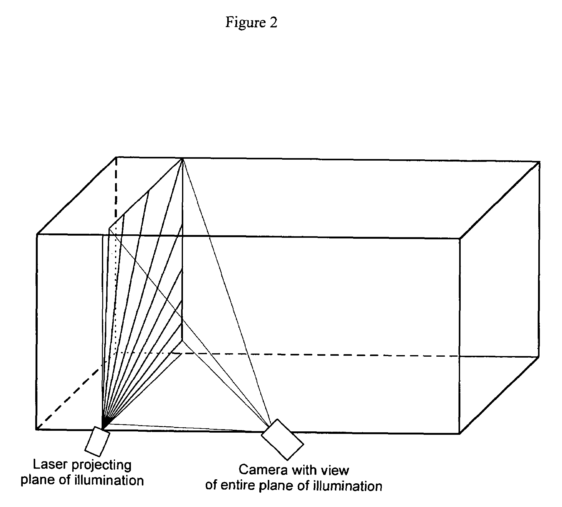
[0033]FIG. 2 is a 3-dimensional diagram of a illumination beam from the laser described in Example 1 in which the beam has been fanned using an optical lens across substantially the whole cross section of a duct; the emitter was positioned at a corner of the duct.

[0034]In a further embodiment of this apparatus, the beam from the laser is mechanically scanned using a stepper motor across substantially the whole cross section of the duct.

example 3

[0035]FIGS. 3 and 4 show diagrammatically an apparatus according to the invention in which back scatter is detected using illumination from a laser emitter having 3 mW output at wavelength 680 nm. The apparatus is mounted at right angles to the direction of gas flow. The illumination from the laser emitter is fanned using an optical line generator which spreads (i.e. fans) the beam in one plane through 80° so that 60% of the cross sectional area of the duct is illuminated. Back scatter is detected using four phototransistors 18 arranged as a square around the emitter 2. The output from the phototransistors is then amplified using high gain AC-coupled amplifiers 20 and summing amp 22 so that any effects of ambient light (including varying changing ambient light) are minimised, and so that only transient sparkles from passing particulate are captured.

[0036]In this embodiment of the apparatus of the invention, the PC stores information received from the amplifiers, and then calculates ...


PUM

PropertyMeasurementUnit
wavelengthaaaaaaaaaa
inclusive angleaaaaaaaaaa

Abstract

An apparatus and method are provided for detecting presence in gas of transient particulate above its normal zero or acceptable level within a duct (4), said apparatus comprising at least one emitter (2) of illumination selected from infra-red, ultraviolet and visible radiation capable of being projected over essentially the entire cross section of the duct (4) and at least one detector (8, 18, 25) for detecting any sparkle of the illumination from the particulate. The apparatus and method are in particular useful for detecting monitoring particulate in areas where build up or presence of particulate can be disadvantageous, for example hospitals and electricity generating stations.

Description

FIELD OF THE INVENTION [0001]This invention relates to particulate detection and in particular to apparatus and methods for the detection, including monitoring of particulate.BACKGROUND OF THE INVENTION [0002]The presence of particulate is in many situations at least a nuisance and at worst catastrophic or illegal. Particulate can carry impurities into locations where its presence is undesirable. Such locations include industrial plant and the environment including air quality monitoring. Thus in the manufacture for example of electronic components the presence of particulate can lead to impurities being included inadvertently in the component, for example, a chip, so rendering the component faulty. Many testing procedures are carried out in areas which are intended to be sterile and particulate free; the presence of particulate may lead to test results from such contaminated areas worthless. In a hospital environment, for example, it is necessary that many wards and, in particular,...

Claims


Application Information

Patent Timeline
Patent Type & Authority Patents(United States)
IPC IPC(8): G08B21/00G01N1/22G01N15/06
CPCG01N1/2247G01N15/06G01N1/2205G01N2015/0693
Inventor WILLIAMS, LEONARD FREDERICK GEORGEBANN, JOHN RICHARDHARRIS, NIGEL EDWARDSIDDONS, JEREMY FRANCIS
Owner POLLUTION CONTROL & MEASUREMENT EURO
Why Eureka
Try Eureka