Liquid crystal panel, and liquid crystal display device

a liquid crystal display and vertical alignment technology, applied in non-linear optics, instruments, optics, etc., can solve the problems of black display color generation, large thickness of liquid crystal panels, and liquid crystal panels that cannot cope with the demand for thin liquid crystal panels, so as to reduce the color of black display and produce thin forms.

Inactive Publication Date: 2009-10-29
NITTO DENKO CORP
View PDF9 Cites 18 Cited by
  • Summary
  • Abstract
  • Description
  • Claims
  • Application Information

AI Technical Summary

Benefits of technology

[0010]An object of the present invention is to provide a liquid crystal panel which can restrain coloration following a change in the viewing angle when black is displayed and can be produced into a thin form; and a liquid crystal display device.

Problems solved by technology

However, when the vertical aligned mode liquid crystal panel is obliquely watched, there remains a problem that coloration is generated in black display by light leakage.
This problem is caused by both of an apparent shift of axes of its two polarizers arranged under a cross nicol condition and the thickness direction retardation of the liquid crystal cell.
However, in the liquid crystal panel in the prior art, it is indispensable to arrange the two retardation films, which have different optical characteristics; therefore, the total thickness of the liquid crystal panel becomes large so that the liquid crystal panel cannot cope with a demand that liquid crystal panels should be made thin.
Furthermore, the cost of this liquid crystal panel is high.

Method used


Image

  • Liquid crystal panel, and liquid crystal display device
  • Liquid crystal panel, and liquid crystal display device
  • Liquid crystal panel, and liquid crystal display device

Examples


reference example 1

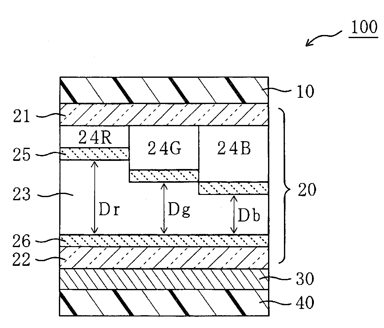
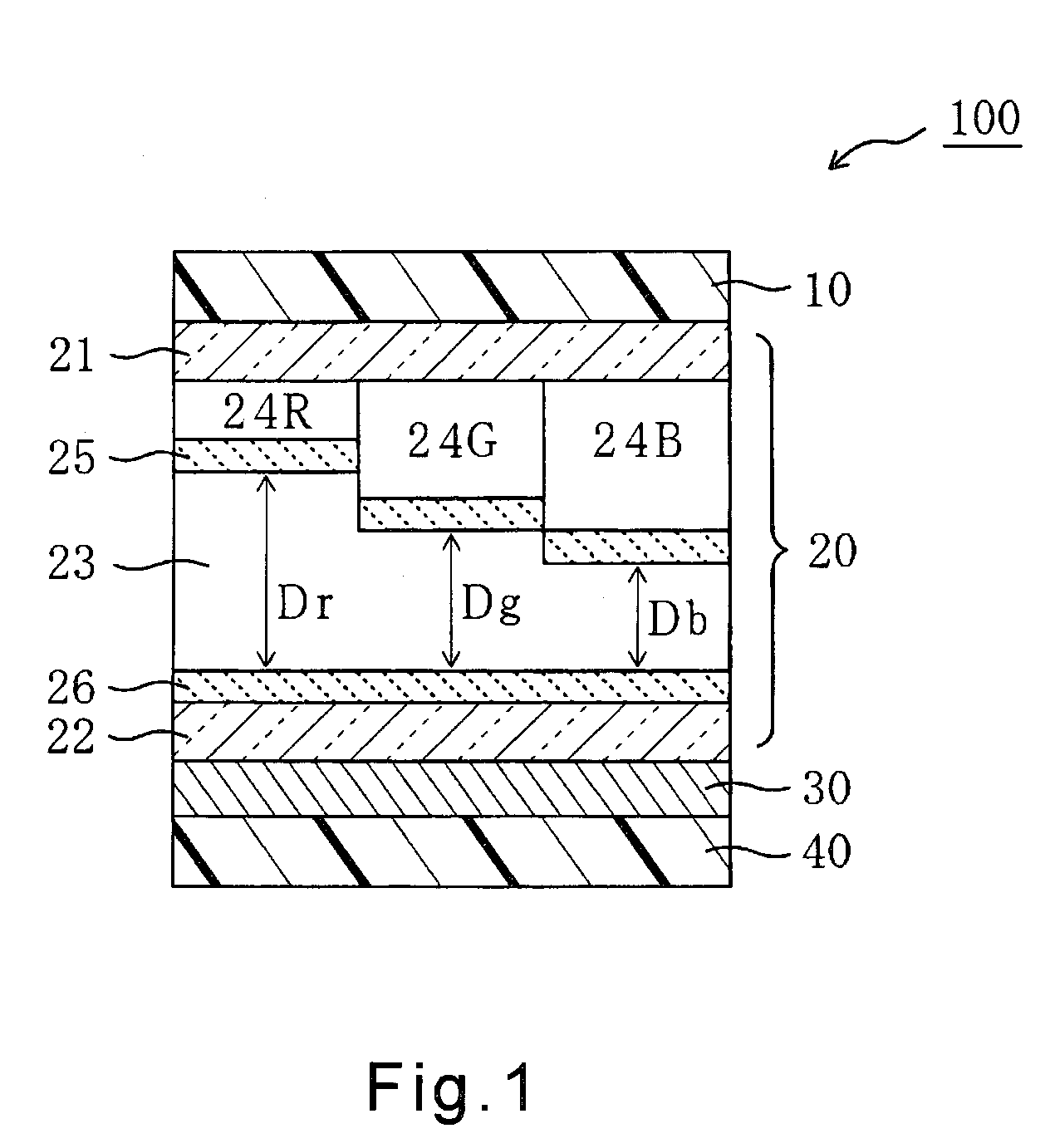
[0176]A liquid crystal panel of Reference Example 1 was made to have the following layer structure from the watching side thereof to the backside: polarizer / triacetylcellulose film / color filter / liquid crystal cell / compensation layer / polarizer.

[0177]The liquid crystal cell was a VA mode. When the thickness of the liquid crystal layer was 3.2 μm, the cells exhibits Rth's in Table 2. As the compensation layer, a single retardation plate exhibiting reverse wavelength dispersion and optical biaxiality (its refractive index ellipsoid being one satisfying nx>ny>nz) was used.

[0178]The Rth's of the triactylcellulose film (referred to as the TAC hereinafter) and the compensation layer were set as shown in Table 2, and the Rth's of the color filter were added thereto (in the present simulation, the Rth's of the color filter were each set to zero, and in the same manner, the Rth's of the color filter were set to zero in each of Reference Examples 2, and Comparative Reference Examples 1 to 3). T...

reference example 2

[0186]A liquid crystal panel of Reference Example 2 was made to have the following layer structure from the watching side thereof to the backside: polarizer / compensation layer / color filter / liquid crystal cell / compensation layer / polarizer.

[0187]As each of the compensation layers arranged on both sides of the liquid crystal cell, a single retardation plate exhibiting reverse wavelength dispersion and optical biaxiality (its refractive index ellipsoid being one satisfying nx>ny>nz) was used.

[0188]The Rth's of the compensation layer were set as shown in Table 2, and the Rth's of the color filter were added thereto (in the present simulation, the Rth's of the color filter were each set to zero). The optimal thicknesses of the individual color regions of the liquid crystal layer were then obtained. Thereafter, in the same way as in Reference Example 1, a simulation was made.

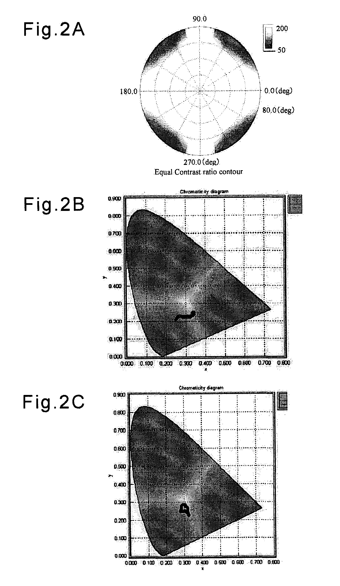
[0189]FIG. 3A shows a contrast cone chart of the liquid crystal panel of Reference Example 2, FIG. 3B shows the colo...


PUM

PropertyMeasurementUnit
wavelengthaaaaaaaaaa

Abstract

The liquid crystal panel of the invention can restrain coloration following a change in the viewing angle when black is displayed, and can be produced into a relatively thin form. This panel has a liquid crystal cell 20 having a color filter having individual blue, green and red regions, a first polarizer 10 formed on one side of the cell 20, a second polarizer 40 formed on the other side of the cell 20, and a compensation layer 30 arranged between the first and second polarizers 10 and 40. The compensation layer 30 has an optical characteristic that the layer gives a larger retardation for a longer wavelength, and the cell 20 has a liquid crystal layer in a vertical alignment mode, and the thickness direction retardation values Rth(B), Rth(G) and Rth(R) of the liquid crystal cell to light transmitted through the individual color regions in the liquid crystal cell 20 satisfy: |Rth(B)|<|Rth(G)|<|Rth(R)|.

Description

BACKGROUND OF THE INVENTION[0001]1. Field of the Invention[0002]The present invention relates to a vertical aligned mode liquid crystal panel, and a liquid crystal display device.[0003]2. Description of the Related Art[0004]In the liquid crystal panel having a liquid crystal layer in vertical aligned mode, the long axis of the liquid crystal material is aligned substantially perpendicularly to its substrate surface when no voltage is applied thereto. Thus, when the liquid crystal panel is watched in the direction perpendicular to the substrate, the panel usually makes it possible to attain substantially complete black display to realize a high contrast.[0005]However, when the vertical aligned mode liquid crystal panel is obliquely watched, there remains a problem that coloration is generated in black display by light leakage.[0006]This problem is caused by both of an apparent shift of axes of its two polarizers arranged under a cross nicol condition and the thickness direction retar...

Claims


Application Information

Patent Timeline
Patent Type & Authority Applications(United States)
IPC IPC(8): G02F1/1335
CPCG02F1/133371G02F1/133514G02F2413/12G02F2001/133637G02F2413/01G02F1/13363G02F1/133637G02F1/1335
Inventor YOSHIMI, HIROYUKITAKEDA, KENTAROU
Owner NITTO DENKO CORP
Why Eureka
Try Eureka