Illumination apparatus, projector, and illumination method

Inactive Publication Date: 2009-11-05
COLUMBIA PEAK VENTURES LLC
View PDF7 Cites 14 Cited by
  • Summary
  • Abstract
  • Description
  • Claims
  • Application Information

AI Technical Summary

Benefits of technology

[0058]According to this configuration, since the combined light beam to be an illumination light beam in the condition of superimposing the light beams from the respective light source sections with each other can be formed, and the ligh

Problems solved by technology

As a result, degradation of the contrast of the display image is caused, and it is not successful to improve the luminance of the display image so much as expected.
Further, since the imaging performance of the projection lens is high in the vicinity of the projection optical axis and drops in accordance the distance from the projection optical axis, the imaging performance of the projection lens cannot sufficiently be exerted, and deterioration of the image quality of the display image is caused.
However, since the secondary light source image has a certai

Method used


Image

  • Illumination apparatus, projector, and illumination method
  • Illumination apparatus, projector, and illumination method
  • Illumination apparatus, projector, and illumination method

Examples


Example

[0092]Hereinafter, a first embodiment of the invention will be explained with reference to FIGS. 1 through 9.

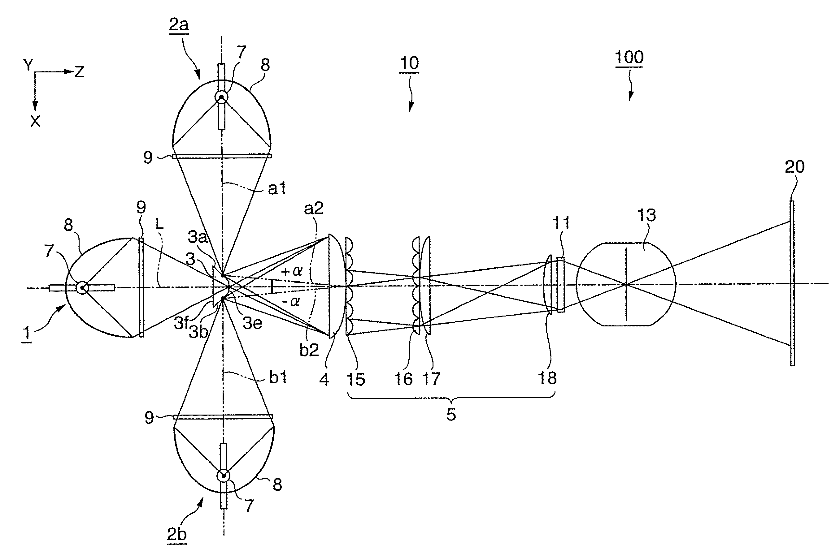
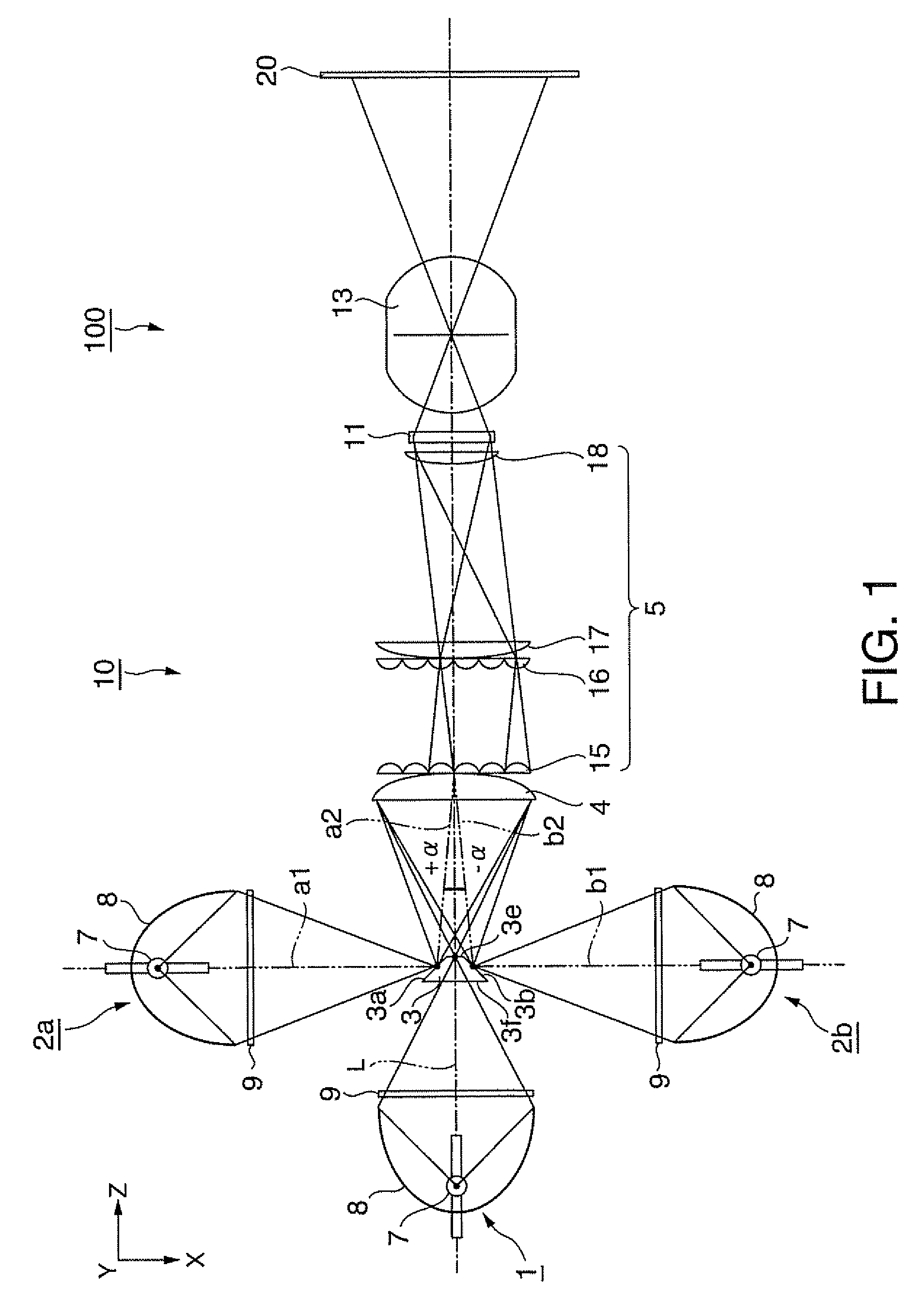
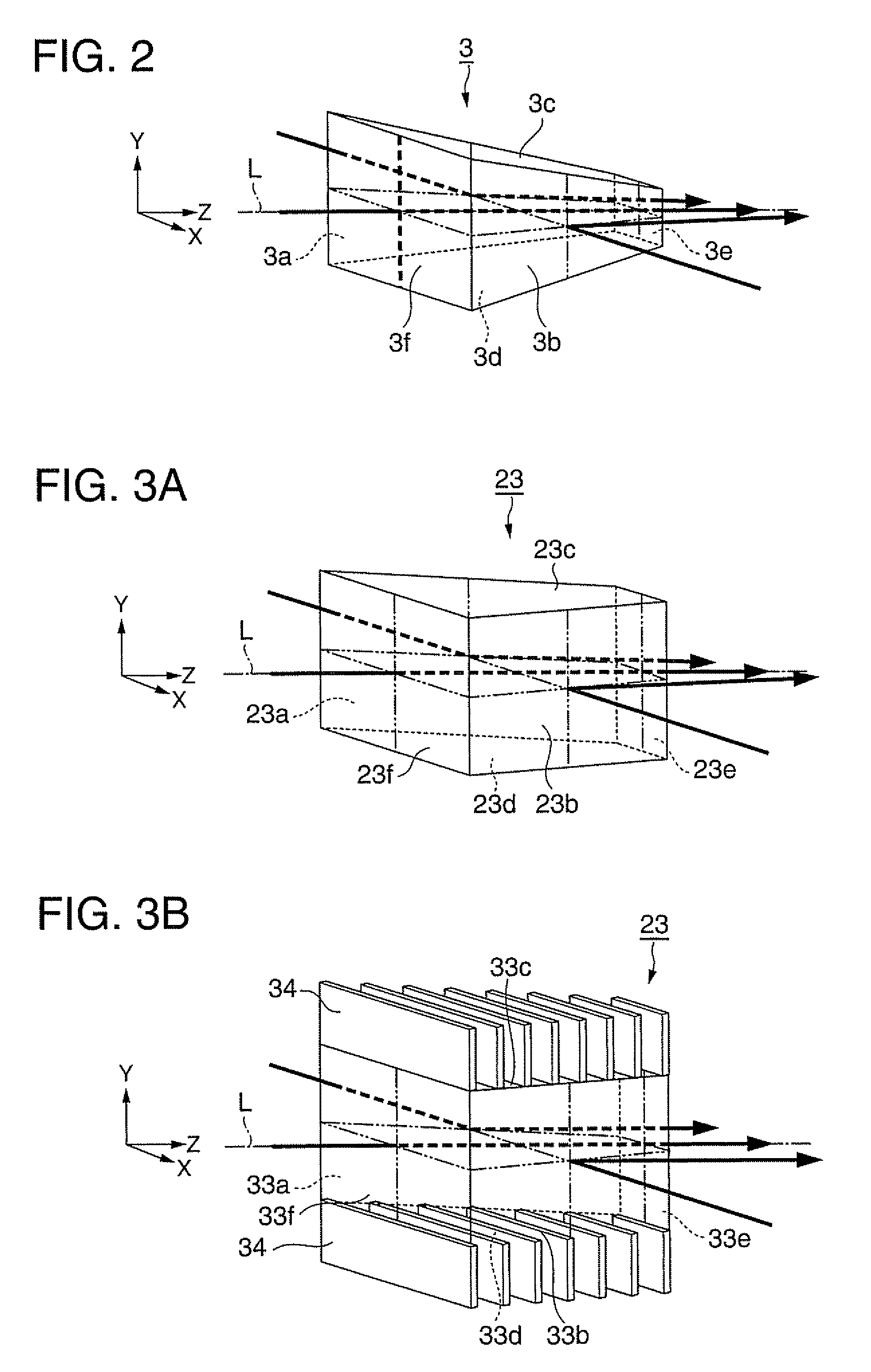
[0093]FIG. 1 is a diagram showing a configuration example of a projector according to the embodiment of the invention. FIGS. 2, 3A, 3B, 4A through 4C are diagrams showing several configuration examples of a reflector used in an illumination optical system of the projector of the present embodiment. FIG. 5 is a diagram showing a light intensity distribution of a converged spot of illumination light. FIG. 6 is a diagram showing angular distributions of light beams input from respective light source sections to a combining lens. FIG. 7 is a diagram showing conditions of light source image formation with respect to the respective light source sections in a second lens array of an integrator section. FIG. 8 is a diagram showing conditions of light source image formation on the pupil plane of a projection lens. FIG. 9 is a diagram showing virtual light intensity distributions on th...

Example

Second Embodiment

[0138]Hereinafter, a second embodiment of the invention will be explained with reference to FIG. 10.

[0139]FIG. 10 is a diagram showing a configuration example of a projector 110 equipped with an illumination optical system according to the embodiment of the invention. It should be noted that in FIG. 10, constituents common to FIG. 1 of the first embodiment are denoted with the same reference symbols, and detailed descriptions therefor will be omitted.

[0140]The point in which an illumination optical system 30 of the present embodiment is different from the illumination optical system of the first embodiment (FIG. 1) is that the second light source sections 2a, 2b not located on the illumination optical axis L are disposed laterally adjacent to the first light source section 1, and the light beams from the second light source sections 2a, 2b are respectively reflected by reflecting mirrors 22 (second light source section dedicated optical axis conversion elements) to ...

Example

Third Embodiment

[0143]Hereinafter, a third embodiment of the invention will be explained with reference to FIGS. 11 through 13.

[0144]FIG. 11 is a diagram showing a configuration example of a projector 120 equipped with an illumination optical system according to the embodiment of the invention. It should be noted that in FIG. 11, constituents common to FIG. 1 of the first embodiment are denoted with the same reference symbols, and detailed descriptions therefor will be omitted.

[0145]The point in which an illumination optical system 40 of the present embodiment shown in FIG. 11 is different from the illumination optical system 10 of the first embodiment is that there are provided a polarization beam splitting prism array 24 (a PBS array) as a polarization converting optical system and a half-wave plate 25. It should be noted that the polarization converting optical system is a technology known to the public, including the relationship in size with the transmission lenses of the secon...


PUM


Abstract

A projector includes an illumination optical system, a light modulation element, and a projection optical system. The illumination optical system includes a first light source section, a plurality of second light source sections, and an optical axis conversion element. The optical axis conversion element emits the light beam, which is input from the first light source section, so that an exit optical axis of the light beam approximately matches with an illumination optical axis, and emits the light beams, which are respectively input from the plurality of second light source sections, so that exit optical axes of the light beams intersect the exit optical axis of the light beam from the first light source section between the optical axis conversion element and the light modulation element.

Description

BACKGROUND[0001]1. Technical Field[0002]The present invention relates to an illumination apparatus for illuminating, for example, a light modulation element, a projector for projecting and displaying an optical image, which is provided to, for example, a light modulation element, on a screen with a projection lens, and an illumination method, and more specifically to a configuration of an illumination optical system of an illumination apparatus and a projector provided with a plurality of light source sections.[0003]2. Related Art[0004]A projector illuminating a small-sized light modulation element, which forms an optical image in accordance with image information, with light from an illumination apparatus, and projecting the optical image on a screen or the like with a projection lens has been put into practical use as one of apparatuses capable of displaying a large-screen image. For such a projector, there have been strongly desired growth in size of the screen and improvement in...

Claims


Application Information

Patent Timeline
IPC IPC(8): G03B21/26F21V33/00G03B21/14
CPCG03B21/14G03B21/2073G03B21/208
Inventor ITOH, YOSHITAKA
Owner COLUMBIA PEAK VENTURES LLC
Why Eureka
Try Eureka