Hydrogen production device and method for producing hydrogen

Active Publication Date: 2011-09-08
SHARP KK
View PDF6 Cites 21 Cited by
  • Summary
  • Abstract
  • Description
  • Claims
  • Application Information

AI Technical Summary

Benefits of technology

[0017]According to the present invention, electromotive force can be generated in the photoelectric conversion part by irradiating the light acceptance surface of the photoelectric conversion part with light, and a potential difference can be generated between the light acceptance surface and the back surface. Thus, a potential difference can be generated between the first gas generation part electrically connected to the back surface of the photoelectric conversion part and the second gas generation part electrically connected to the light acceptance surface of the photoelectric conversion part through the first conductive part. By bringing an electrolytic solution into contact with the first gas generation part and the second gas generation part having the potential difference therebetween, H2 can be generated from the electrolytic solution in one of the first gas generation part and the second gas generation part, and O2 can be generated from the electrolytic solution in the other thereof. Thus, hydrogen can be produced by collecting the generated H2.
[0018]According to the present invention, since the hydrogen generation part and the oxygen generation part are provided on the back surface of the photoelectric conversion part, the light can enter the light acceptance surface without passing through the electrolytic solution, so that the incident light can be prevented from being absorbed and the incident light can be prevented from being scattered by the electrolytic solution. Thus, the incident light amount entering the photoelectric conversion part can be large, and the light use efficiency can be high.
[0019]In addition, according to the present

Problems solved by technology

While many solar cell techniques and solar heat utilization techniques have been already put to practical use, these techniques are being developed to be improved because energy use efficiency is still low and costs to produce electricity and heat are still high.
Furthermore, although the energy in the forms of

Method used


Image

  • Hydrogen production device and method for producing hydrogen
  • Hydrogen production device and method for producing hydrogen
  • Hydrogen production device and method for producing hydrogen

Examples


Example

1. Example 1

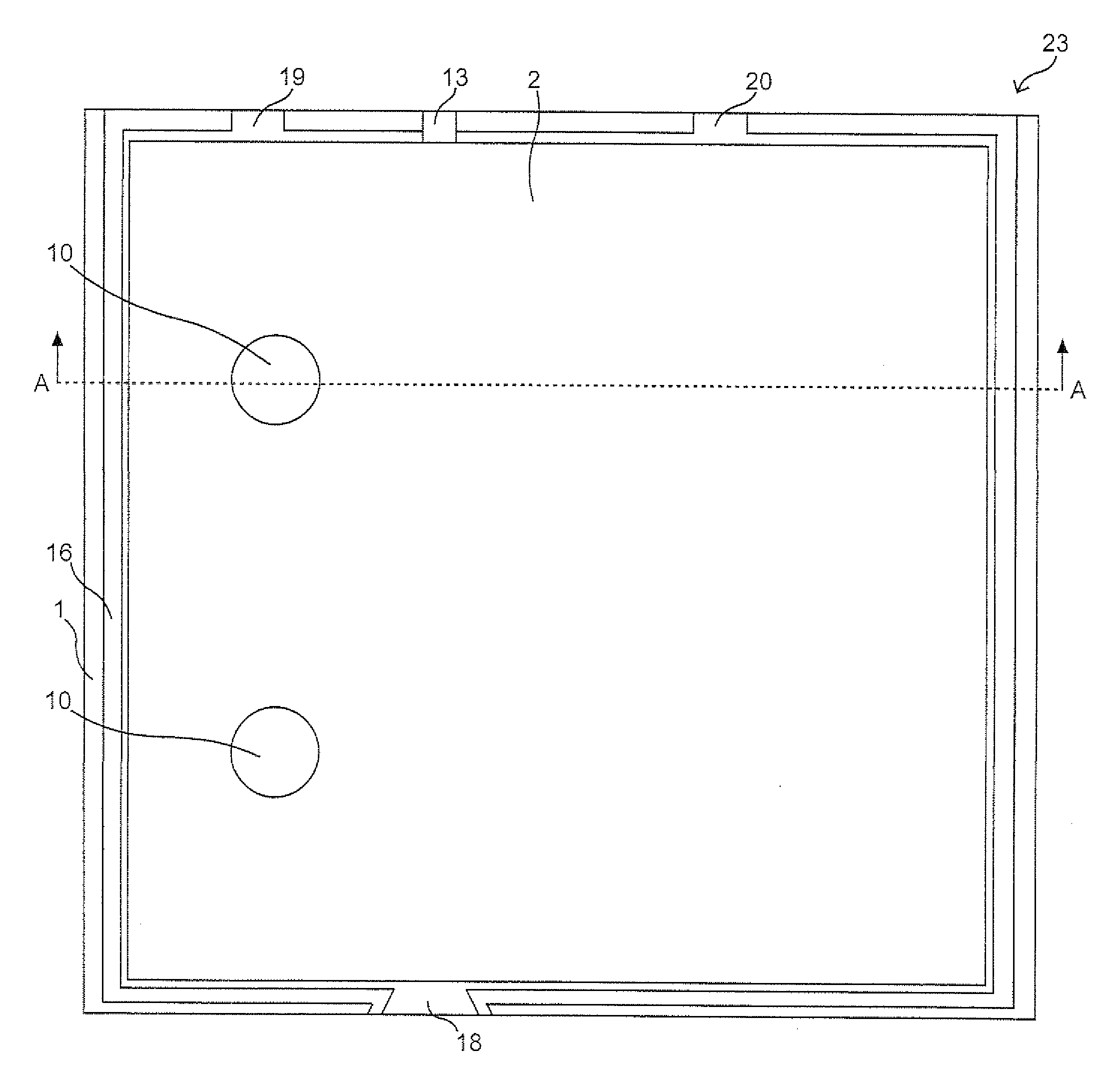
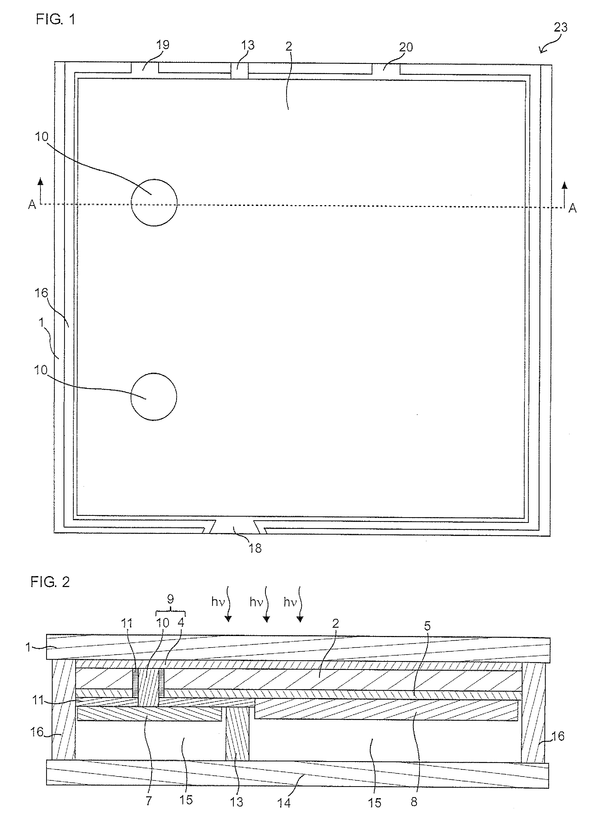
[0190]The following hydrogen production device as shown in FIGS. 1 to 3 was produced.

[0191]In the produced hydrogen production device, an SnO2 thin film serving as the first electrode 4 is formed on a glass substrate serving as the substrate 1. The two-junction photoelectric conversion part 3 formed of an a-SiGe layer and an a-Si layer is laminated on the first electrode 4, and the second electrode 5 formed of a transparent electrode layer made of indium tin oxide (ITO) is provided thereon. The hydrogen generation part (first gas generation part 8) supporting the hydrogen generation catalyst is provided on the second electrode 5, while the oxygen generation part (second gas generation part 7) supporting the oxygen generation catalyst is provided so as to be isolated from the second electrode 5 with the insulation part 11 formed of a polyimide film and connected to the first electrode 4 through the second conductive part 10 made of an Ag paste. The electrolytic solution p...

Example

2. Example 2

[0197]The hydrogen production device as shown in FIG. 4 was produced on the following condition.

[0198]The photoelectric conversion part 2, the second electrode 5, the insulation part 11, the second conductive part 10, the oxygen generation part (second gas generation part 7), and the hydrogen generation part (first gas generation part 8) were formed on the substrate 1 by the same method as in the example 1. Here, this example is different from the example 1 in that the contact hole having the second conductive part 10 is provided along a longitudinal axis direction of the second gas generation part 7. In this case, since the number of the contact holes is reduced, a contact defect can be prevented, and a contact can be formed such that a cross-section area of the contact hole is narrower than a width of the second gas generation part 7 connected to the second conductive part 10 even when the width of the second gas generation part 7 is narrowed, so that hydrogen and oxyg...

Example

3. Example 3

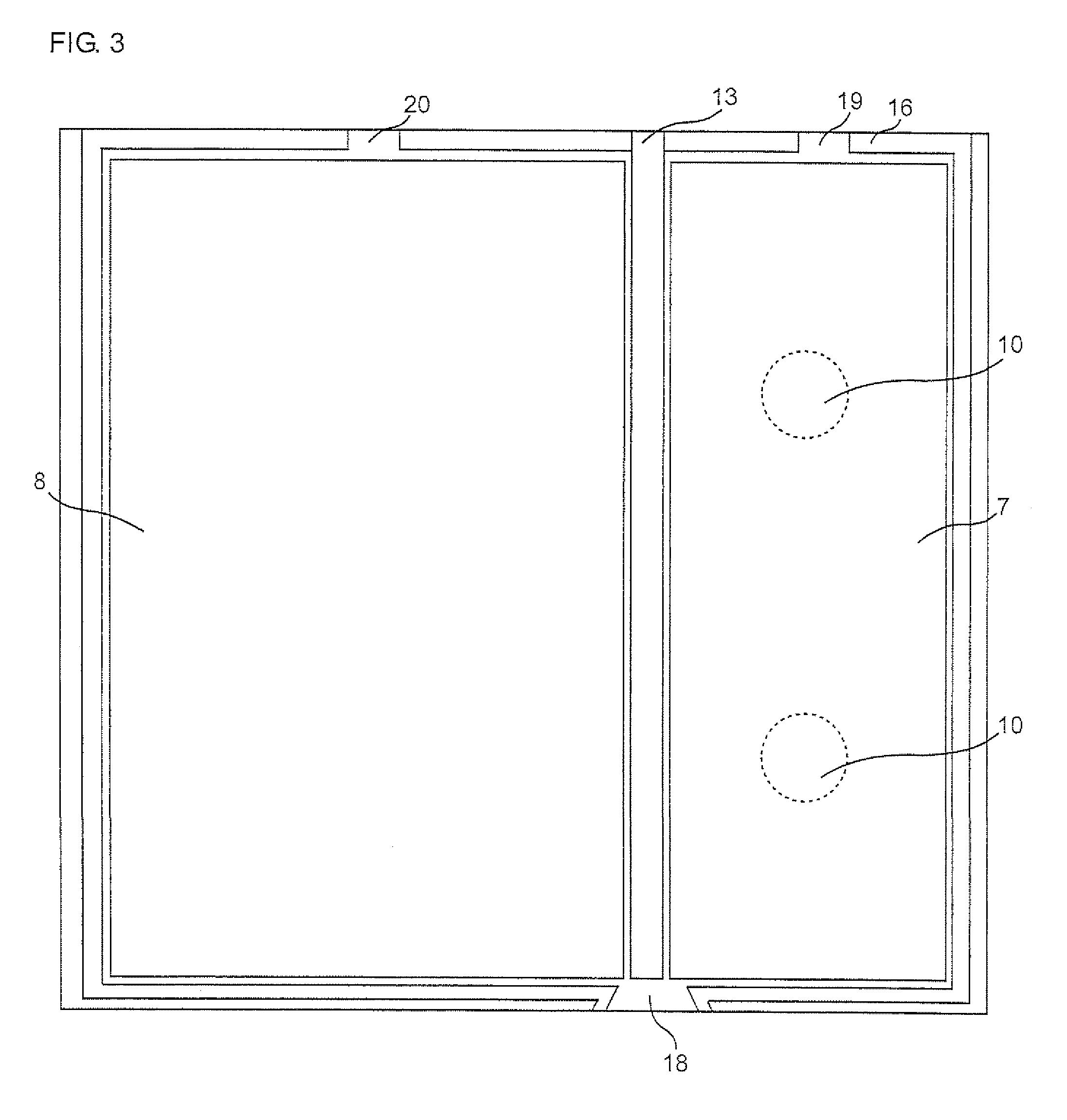
[0199]The hydrogen production device as shown in FIG. 5 was produced on the following condition.

[0200]The photoelectric conversion part 2, the second electrode 5, the insulation part 11, the second conductive part 10, the oxygen generation part (second gas generation part 7), and the hydrogen generation part (first gas generation part 8) were formed on the substrate 1 by the same method as in the example 1.

[0201]Then, as shown in FIG. 5, the partition wall 13 was formed by applying thermal curing polyimide to a position between the first gas generation part 8 and the second gas generation part 7 by a screen printing method so that the gas can be efficiently collected, and then the device was sealed by connecting the material on the substrate and the plate with the seal material. Thus, the hydrogen production device was produced.


PUM

PropertyMeasurementUnit
Fractionaaaaaaaaaa
Fractionaaaaaaaaaa
Electrical conductoraaaaaaaaaa

Abstract

There is provided a hydrogen production device high in light use efficiency and capable of producing hydrogen with high efficiency.
The hydrogen production device according to the present invention includes a photoelectric conversion part having a light acceptance surface and a back surface, a first gas generation part provided on the back surface, and a second gas generation part provided on the back surface, in which one of the first gas generation part and the second gas generation part is a hydrogen generation part to generate H2 from an electrolytic solution, another one thereof is an oxygen generation part to generate O2 from the electrolytic solution, the first gas generation part is electrically connected to the back surface, and the second gas generation part is electrically connected to the light acceptance surface via a first conductive part.

Description

TECHNICAL FIELD[0001]The present invention relates to a hydrogen production device and a method for producing hydrogen.BACKGROUND ART[0002]Recently, renewable energy is expected to be used in view of exhaustion of fossil fuel resources and emission limitation of global greenhouse gas. The renewable energy is generated from various kinds of resources such as sunlight, hydro power, wind power, geothermal heat, tidal power, and biomass, among which, since the sunlight is large in utilizable energy amount and relatively small in geographical constraint as compared with the other renewable energy resources, a technique to efficiently produce utilizable energy from the sunlight is expected to be developed and become widely used in an early stage.[0003]The utilizable energy produced from the sunlight include electric energy produced by a solar cell or a solar thermal turbine, thermal energy produced by collecting solar energy to a heat medium, and stockable fuel energy such as a liquid fue...

Claims


Application Information

Patent Timeline
IPC IPC(8): C25B1/02C25B9/08C25B9/00C25B9/19C25B9/17
CPCC01B3/04C01B13/0203Y02E60/366Y02E60/364C25B1/003Y02E60/36C25B1/55
Inventor YOSHIDA, AKIHITOSATA, SHUNSUKEKAGA, MASAKI
Owner SHARP KK
Why Eureka
Try Eureka