
Light source unit for thermally-assisted magnetic recording

Active Publication Date: 2011-06-02
TDK CORPARATION
View PDF19 Cites 36 Cited by
  • Summary
  • Abstract
  • Description
  • Claims
  • Application Information

AI Technical Summary

Benefits of technology

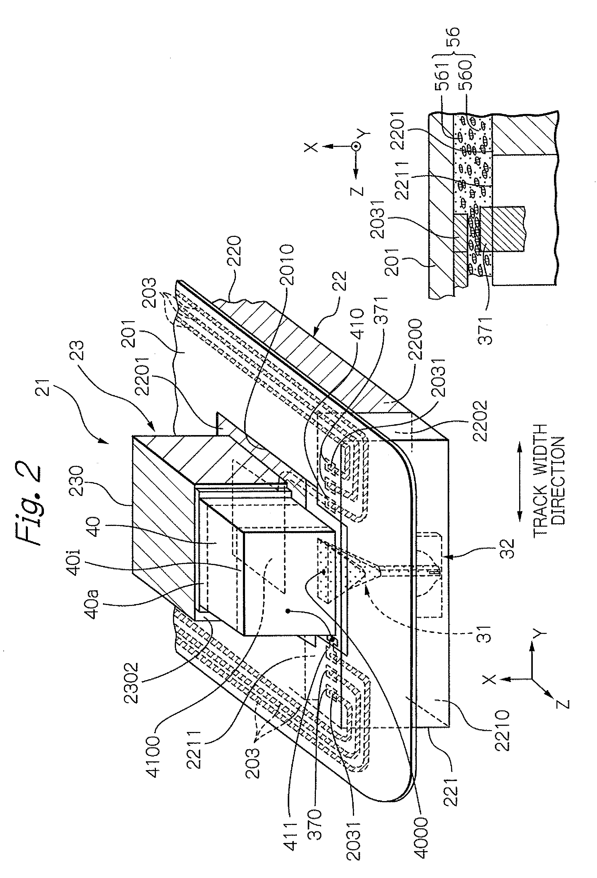
[0024]In the light source unit according to the present invention, there is no need to provide a terminal electrode for light source on the source-integration surface because of the provision of the first and second electrodes. As a result, the weight of the light source unit can be reduced while ensuring power supply to the light source. Here, the light source is preferably an edge-emitting laser diode, and it is preferable that the light source is provided by bonding an electrode layer of the two electrode layers onto the second electrode, the electrode layer being opposite to a ridge structure. In the case, alignment of the light source and the unit substrate that comprises the first and second electrodes can be performed by means of a positioning jig having a flat surface without butting the light-emission center of the light source against the flat surface of the positioning jig.
[0025]Further, in the light source unit according to the present invention, it is preferable that a distance DREC between a surface that includes the light-emission center of the light source and a surface of the first electrode in a direction perpendicular to the first electrode surface is zero or more, and 5 micrometers (μm) or less. Since the distance DREC is greater than or equal to 0, the light-emitting surface of the light source does not protrude from the light source unit. Consequently, the light source is prevented from being subjected to excessive mechanical stress and damage during bonding. Furthermore, since the direction DREC is less than or equal to 5 μm, the distance between the light-emission center and the light-receiving end surface of the optical system disposed on the back surface of the slider is sufficiently small and therefore a high light use efficiency can be provided.
[0039]In the manufacturing method of the light source unit according to the present invention, because a positioning jig comprising a flat surface is used and the electrode layer of the light source opposite to the ridge structure and the second electrode are bonded to each other, a portion of the light-emitting surface can be easily butted against the flat surface while preventing the light-emission center from hitting the flat surface. Consequently, the positioning of the light source and the unit substrate relative to each other can be accomplished with a high degree of accuracy without applying an excessive mechanical stress to the light source. Therefore, the light-emission center and the light-receiving end surface of the optical system can be disposed sufficiently close to each other in the completed thermally-assisted magnetic recording head. As a result, a sufficiently high light use efficiency is achieved.
[0040]Further, the above-explained positioning does not need any sophisticated image recognition technology or high-precision positioning mechanism. Consequently, the production does not require so expensive a facility or prolonged tact time for production. Therefore, the per-head-chip production cost can be kept sufficiently low.

Problems solved by technology

However, the decrease in size of the magnetic grains raises a problem of degradation in thermal stability of the magnetization due to the decrease in volume.
As a result, the head cannot write data to the magnetic recording medium when the anisotropic magnetic field of the medium exceeds the write field limit.
However, from the beginning, more significant problem to be solved exists in where and how a light source with a sufficiently high output of light should be disposed inside a head.
Consequently, a considerably expensive production facility is required for the production, and the tact time required for the production also tends to increase.
Accordingly, per-head-chip cost can increase.

Method used


Image

  • Light source unit for thermally-assisted magnetic recording
  • Light source unit for thermally-assisted magnetic recording
  • Light source unit for thermally-assisted magnetic recording

Examples


Embodiment Construction

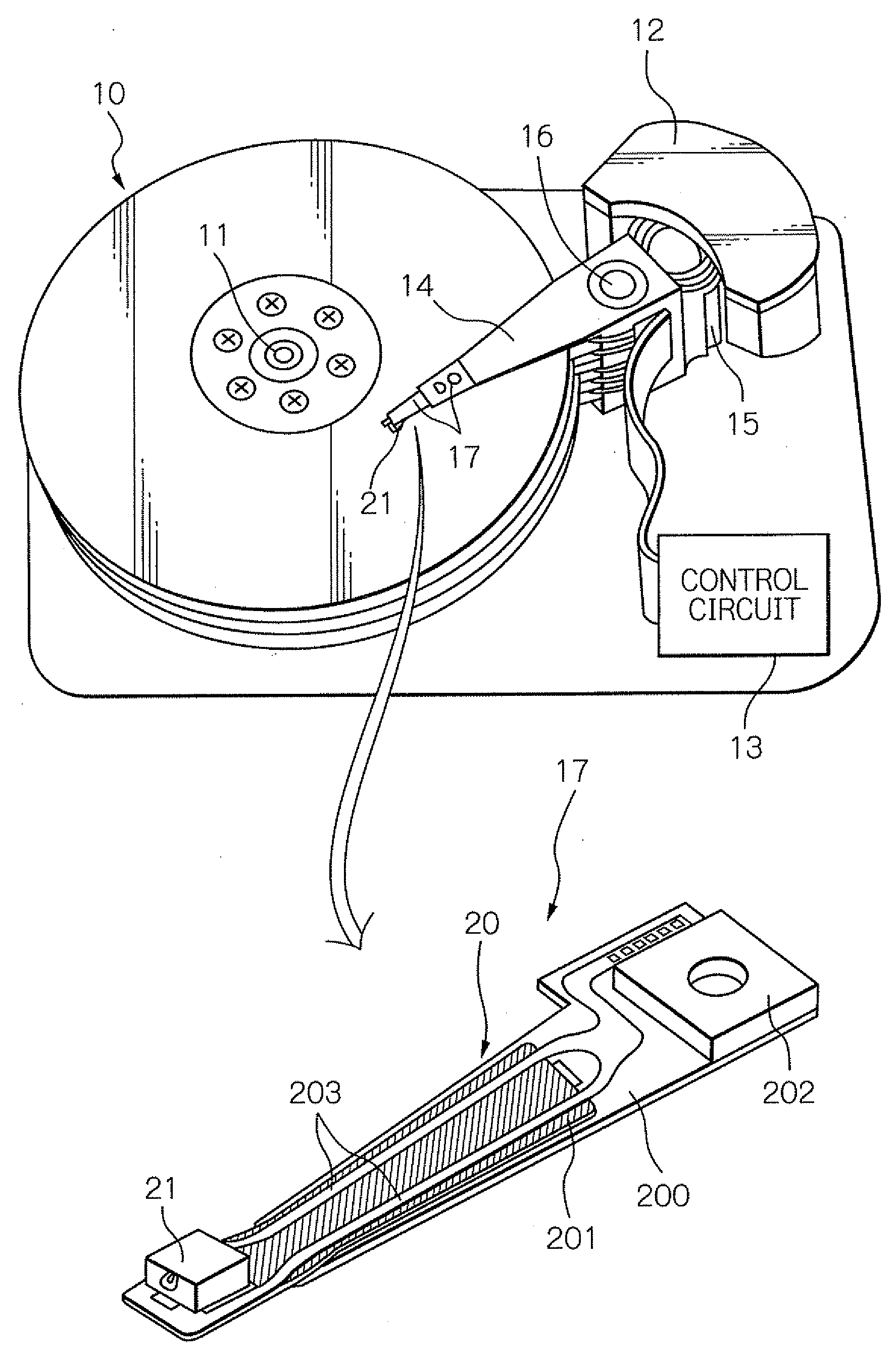
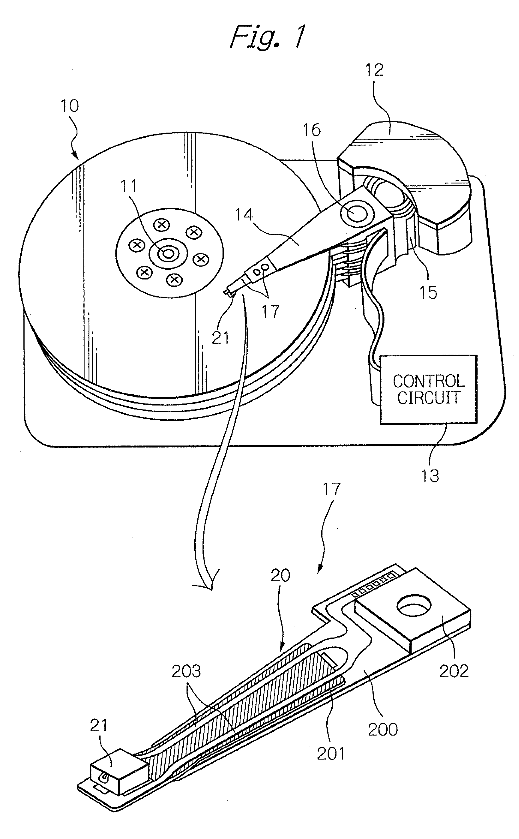
[0051]FIG. 1 shows a perspective view schematically illustrating a structure of a major part in one embodiment of a magnetic recording apparatus and a head gimbal assembly (HGA) according to the present invention. Here, in the perspective view of the HGA, the side of the HGA opposed to the surface of the magnetic disk is presented as the upper side.

[0052]A magnetic disk apparatus as a magnetic recording apparatus shown in FIG. 1 includes: a plurality of magnetic disks 10 rotating around a rotational axis of a spindle motor 11; an assembly carriage device 12 provided with a plurality of drive arms 14 thereon; an HGA 17 attached on the top end portion of each drive arm 14 and provided with a thermally-assisted magnetic recording head 21; and a recording / reproducing and light-emission control circuit 13 for controlling write / read operations of the thermally-assisted magnetic recording head 21 and further for controlling the emission operation of a laser diode as a light source that gen...


PUM

PropertyMeasurementUnit
Distanceaaaaaaaaaa
Weightaaaaaaaaaa
Widthaaaaaaaaaa

Abstract

Provided is a light source unit the weight of which can be reduced while ensuring power supply to the light source. The light source is configured to form a thermally-assisted magnetic recording head by being joined with a slider including an optical system that propagates light for thermal assist. The light source unit comprises: a unit substrate including a joining surface that faces an power-supply electrode of the slider; a first electrode provided on the joining surface; a second electrode provided on a source-installation surface and electrically connected to the first electrode; and a light source that includes two electrode layers and a light-emission center located in a light-emitting surface. The first and second electrodes eliminate the provision of a terminal electrode for light source on the source-integration surface. As a result, the weight of the light source unit can be reduced.

Description

BACKGROUND OF THE INVENTION[0001]1. Field of the Invention[0002]The present invention relates to a light source unit including a light source for performing thermally-assisted magnetic recording, and to a magnetic recording head provided with the light source unit. Further, the present invention relates to a method for manufacturing the light source unit.[0003]2. Description of the Related Art[0004]As the recording densities of magnetic recording apparatuses become higher, as represented by magnetic disk apparatuses, further improvement has been required in the performance of thin-film magnetic heads and magnetic recording media. As the thin-film magnetic heads, a composite-type thin-film magnetic head is widely used, which has a stacked structure of a magnetoresistive (MR) element for reading data and an electromagnetic transducer for writing data.[0005]Whereas, the magnetic recording medium is generally a kind of discontinuous body of magnetic grains gathered together, and each of...

Claims


Application Information

Patent Timeline
IPC IPC(8): G11B11/00H01S4/00G11B5/02H01S5/02375
CPCG11B5/314G11B5/6088G11B2005/001G11B2005/0021Y10T29/49002H01S5/02268H01S5/02272H01S5/4031G11B5/105H01S5/005H01S5/02375H01S5/0237
Inventor SHIMAZAWA, KOJIITO, YASUHIROSHINDO, OSAMUFUJII, RYUJI
Owner TDK CORPARATION
Learn More