
Light guide element, image display device, and sensing apparatus

Pending Publication Date: 2021-10-07
FUJIFILM CORP
View PDF0 Cites 1 Cited by
  • Summary
  • Abstract
  • Description
  • Claims
  • Application Information

AI Technical Summary

Benefits of technology

The present invention provides a light guide element that can emit incident light with high light use efficiency. This element can extend the FOV for use in AR glasses or the like, allowing for a broader range of observation. The image display device and sensing apparatus that include this element can display and sense at a wider field of view. This improvement in light use efficiency and FOV enables better observation and analysis of images.

Problems solved by technology

Therefore, light use efficiency is low, and for example, in a case where the optical waveguide is used for AR glasses or the like, an image to be observed by a user is darker than an image displayed by a display device.

Method used


Image

  • Light guide element, image display device, and sensing apparatus
  • Light guide element, image display device, and sensing apparatus
  • Light guide element, image display device, and sensing apparatus

Examples


reference example 1

[0443](Formation of Alignment Film)

[0444]A glass substrate was used as the support. The following alignment film-forming coating solution was applied to the support by spin coating. The support on which the coating film of the alignment film-forming coating solution was formed was dried using a hot plate at 60° C. for 60 seconds. As a result, an alignment film was formed.

Alignment Film-Forming Coating SolutionThe following material for photo-alignment 1.00 part by massWater16.00 parts by massButoxyethanol42.00 parts by massPropylene glycol monomethyl ether42.00 parts by mass-Material for Photo-Alignment-

[0445](Exposure of Alignment Film)

[0446]The alignment film was exposed using the exposure device shown in FIG. 15 to form an alignment film P-1 having an alignment pattern.

[0447]In the exposure device, a laser that emits laser light having a wavelength (325 nm) was used as the laser. The exposure dose of the interference light was 300 mJ / cm2. The single period (the length over which ...

reference example 2

[0460]Methyl ethyl ketone was applied to the first A diffraction element according to Reference Example 1 by spin coating, and an alignment film was formed on the first A diffraction element using the same method as that during the formation of the first A diffraction element. The alignment film was exposed using the same method as that during the formation of the first A diffraction element, except that the alignment pattern was formed by exposing the alignment film in a state where each of the optical axes of the λ / 4 plates 72A and 72B of the exposure device shown in FIG. 15 was rotated by 90°. By forming the cholesteric liquid crystal layer on the alignment film using the same method as that of the first A diffraction element, the first B diffraction element was formed.

[0461]As a result, the first A diffraction element and the first B diffraction element having opposite one in-plane directions in which the optical axis of the liquid crystal compound rotated were laminated to prep...

reference example 3

[0462]The first A diffraction element was prepared using the same method as that of Reference Example 1.

[0463]A first B diffraction element was formed using the same method as that during the formation of the cholesteric liquid crystal layer of the first A diffraction element, except that the composition A-1 was changed to the composition of the first B diffraction element according to Reference Example 1. The formed first A diffraction element and the formed first B diffraction element were bonded to each other to be adjacent to each other on another glass substrate using an adhesive (SK DINE 2057, manufactured by Soken Chemical & Engineering Co., Ltd.). In this case, the one in-plane directions in which the optical axis of the liquid crystal compound rotated were the same.

[0464]As a result, the first A diffraction element and the first B diffraction element having the same one in-plane direction in which the optical axis of the liquid crystal compound rotated were disposed to be a...


PUM


Abstract

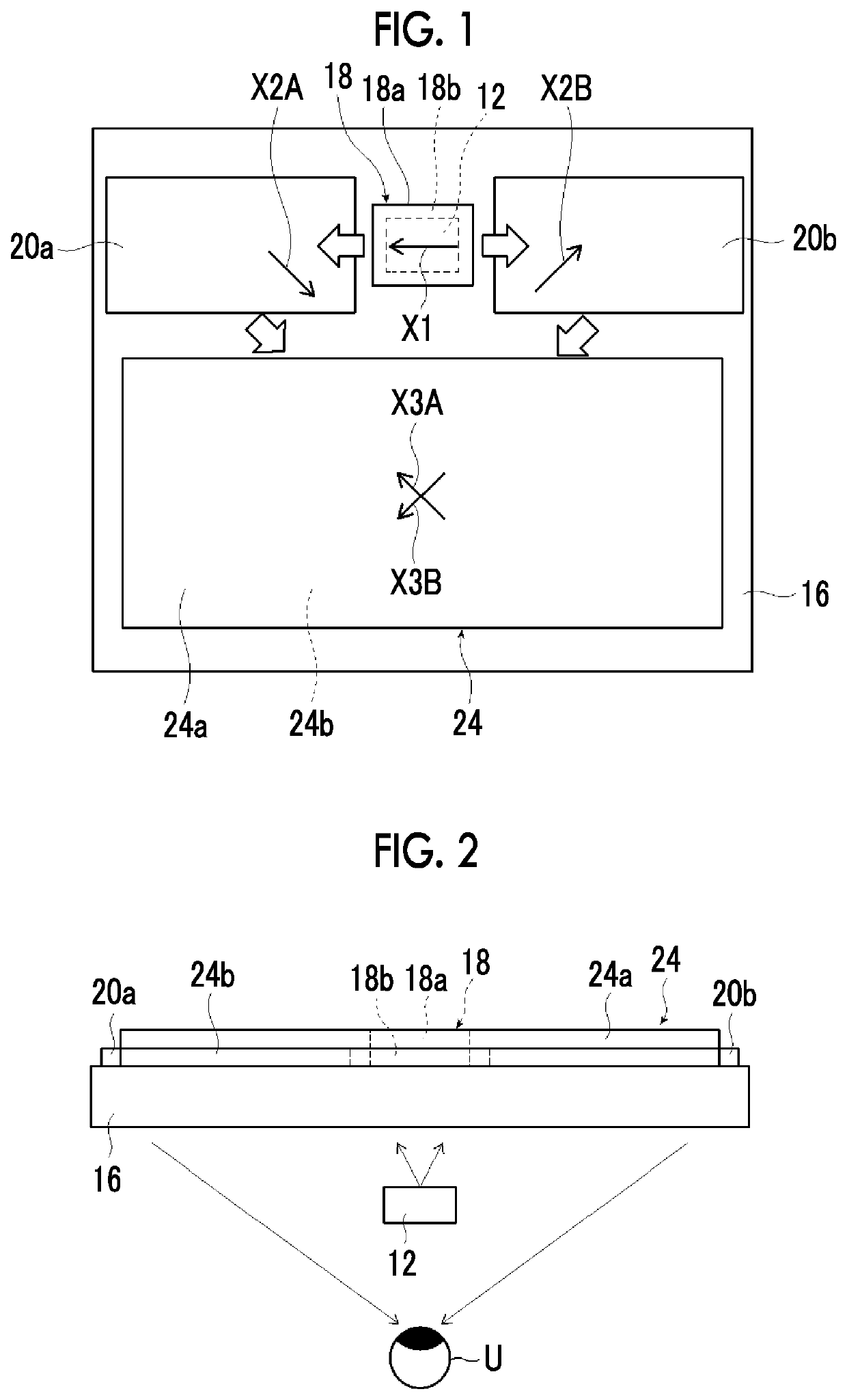
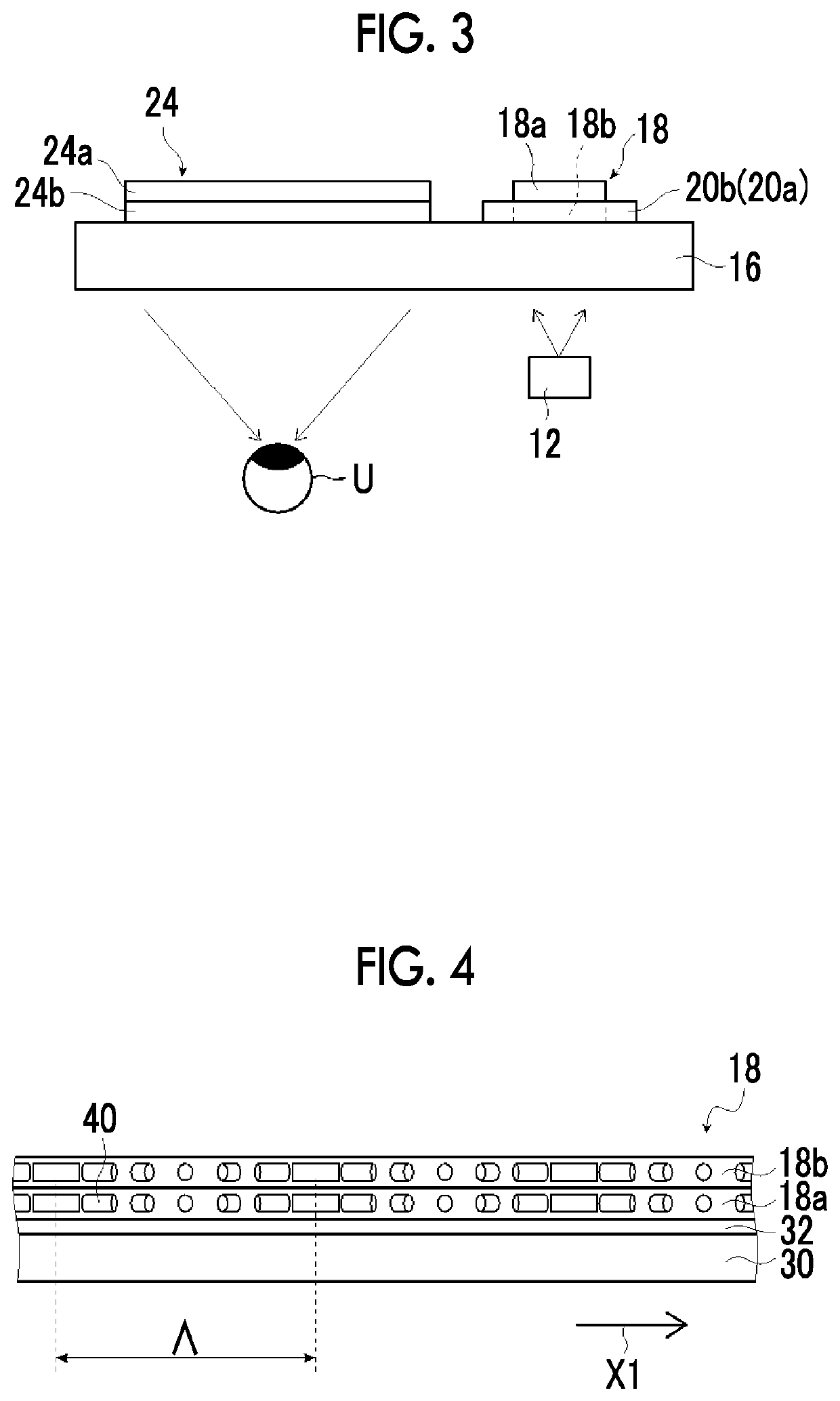
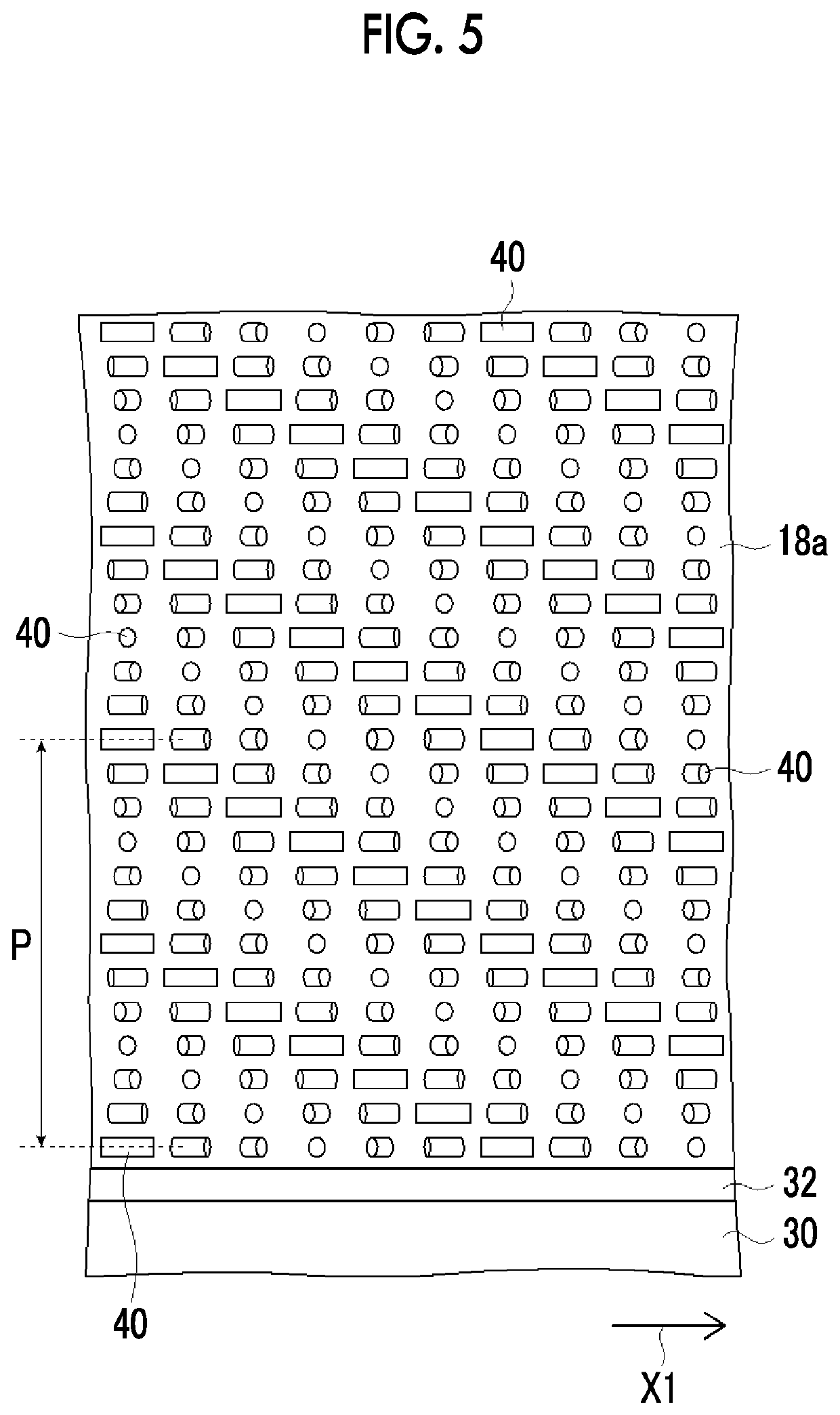
Provided are a light guide element in which incidence light can be emitted with high use efficiency and a wide FOV can be obtained for use in AR glasses, and an image display device and a sensing apparatus that include the light guide element. The light guide element includes a light guide plate and first to third diffraction elements, in which the first diffraction element diffracts incidence light in two or more different directions to be incident into the light guide plate, the second diffraction element includes a plurality of diffraction elements that diffract the light to the third diffraction element, the third diffraction element emits the light from the light guide plate, and at least one of the first diffraction element or the third diffraction element has a liquid crystal alignment pattern in which a direction of an optical axis derived from the liquid crystal compound changes while continuously rotating in at least one in-plane direction.

Description

CROSS-REFERENCE TO RELATED APPLICATIONS[0001]This application is a Continuation of PCT International Application No. PCT / JP2019 / 048512 filed on Dec. 11, 2019, which claims priority under 35 U.S.C. § 119(a) to Japanese Patent Application No. 2018-231788 filed on Dec. 11, 2018. Each of the above applications is hereby expressly incorporated by reference, in its entirety, into the present application.BACKGROUND OF THE INVENTION1. Field of the Invention[0002]The present invention relates to a light guide element that propagates light, and an image display device and a sensing apparatus that include the light guide element.2. Description of the Related Art[0003]Recently, as described in Bernard C. Kress et al., Towards the Ultimate Mixed Reality Experience: HoloLens Display Architecture Choices, SID 2017 DIGEST, pp.127-131, augmented reality (AR) glasses that display a virtual image and various information or the like to be superimposed on a scene that is actually being seen have been pu...

Claims


Application Information

Patent Timeline
IPC IPC(8): G02B6/34G02B27/01F21V8/00G02B27/00G02B6/10G02B5/18
CPCG02B6/34G02B27/0101G02B6/0016G02B5/1828G02B27/0093G02B6/102G02B6/0036G02B6/00G02B5/1866G02B27/0172G02B2027/0123
Inventor SATO, HIROSHISAITOH, YUKITOSASATA, KATSUMI
Owner FUJIFILM CORP
Learn More