Lighting Device and Projector

Active Publication Date: 2013-01-03
PANASONIC CORP
View PDF5 Cites 34 Cited by
  • Summary
  • Abstract
  • Description
  • Claims
  • Application Information

AI Technical Summary

Benefits of technology

[0005]In general, the luminous flux of the light emitted from a solid-state light source such as a semiconductor laser or a light-emitting diode is small compared with that from a discharge lamp. Consequently, as a technique toward heightening the brightness of a projector employing a solid-state light source, methods that serve to increase the luminous flux by utilizing a fluorescent light source in which multiple laser beam sources are employed to excite a fluorescent material to cause fluorescent emission hold promise. The emission spectrum of the fluorescent light source depends on the fluorescent material but has a relatively slighter blue component. Thus, it is beneficial to use a blue semiconductor laser or a blue light-emitting diode for a blue component in combination with a fluorescent light source to conf

Problems solved by technology

Discharge lamps carry with their problems of

Method used


Image

  • Lighting Device and Projector
  • Lighting Device and Projector
  • Lighting Device and Projector

Examples


embodiment 1

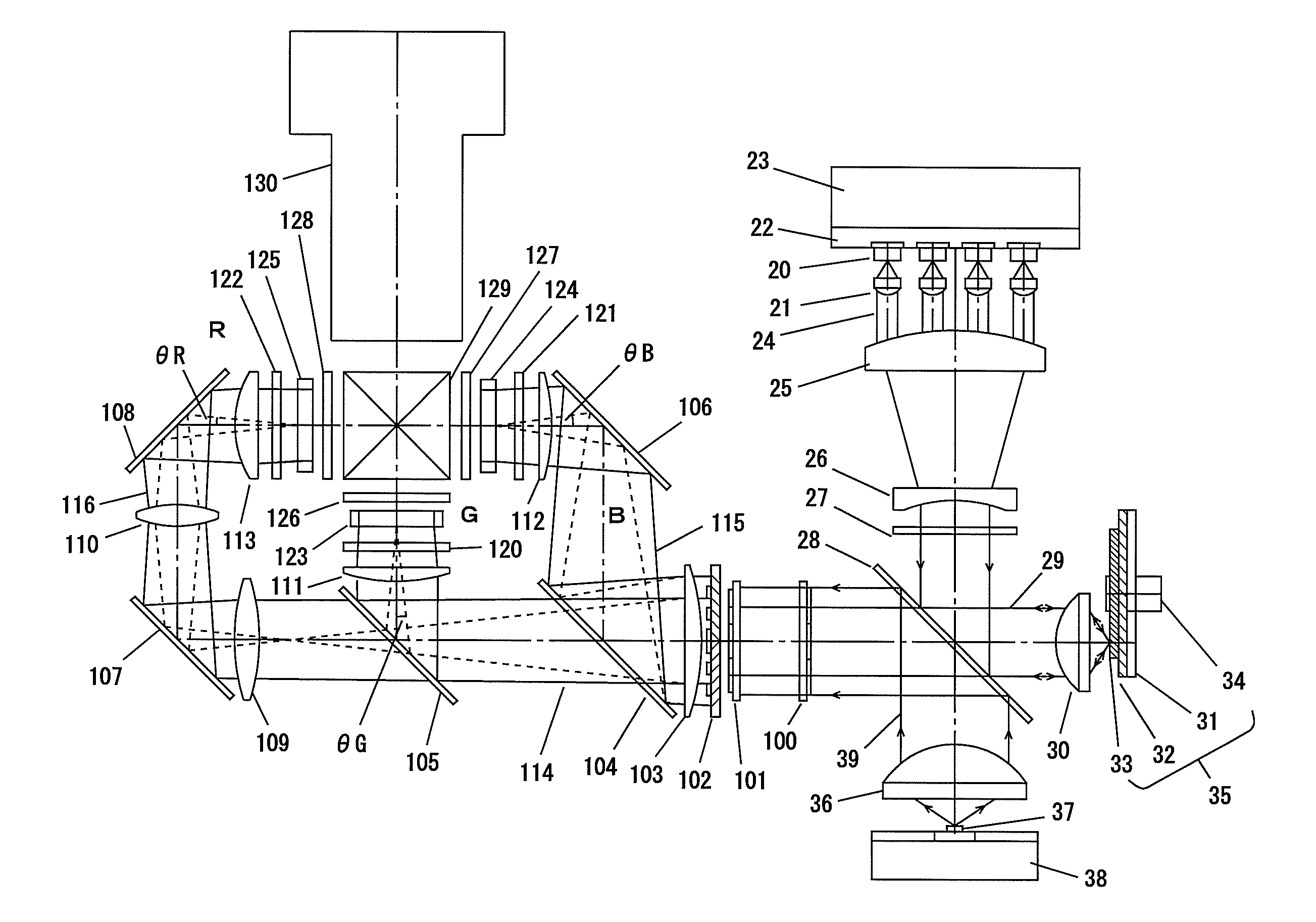
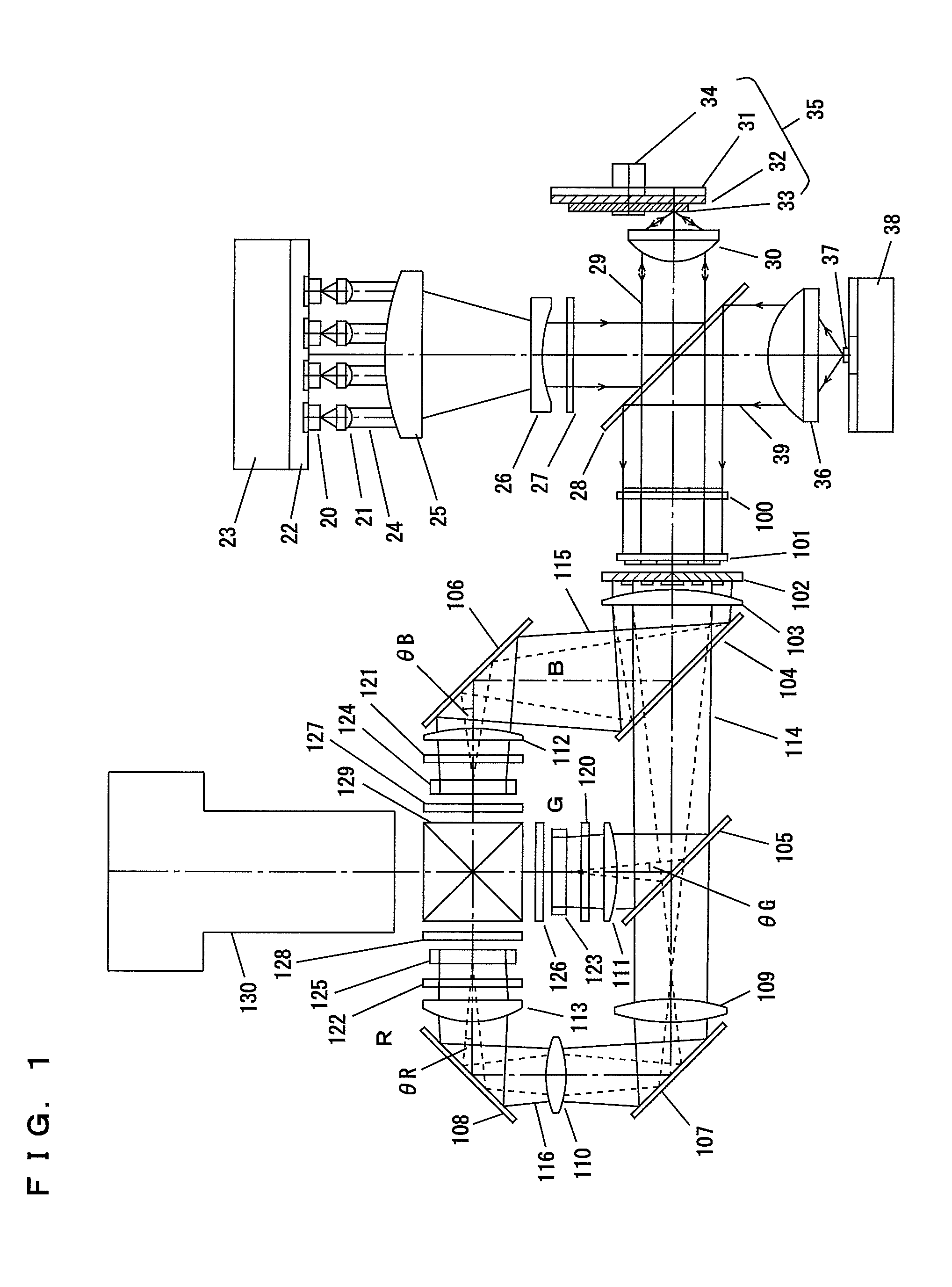
[0018]FIG. 1 is a configurational diagram of a lighting device showing an embodiment of the present disclosure and a projector that uses the lighting device as an illumination light source for image formation elements. As the image formation elements, for example, light valves are used, each of which is a TN-mode or VA-mode active matrix transmission-type liquid crystal panel in which thin-film transistors are formed in the pixel region.

[0019]Reference numeral 20 indicates a semiconductor laser; reference numeral 21 indicates a converging lens; reference numeral 22 indicates a heat dissipation plate; reference numeral 23 indicates a heat sink; reference numerals 25 and 26 indicate lenses; reference numeral 27 indicates a diffusion plate; reference numeral 28 indicates a blue-reflecting dichroic mirror; reference numeral 30 indicates a condensing lens that is first light-converging optics; reference numeral 35 indicates a fluorescent baseplate, with the fluorescent baseplate being a ...

embodiment 2

[0036]FIG. 5 is a configurational diagram of a lighting device showing an embodiment of the present disclosure and a projector that uses the lighting device as an illumination light source for image formation elements. What is different from the configuration of Embodiment 1 of the present disclosure is that an illumination optical system includes first and second illumination optics having different f-numbers for first and second light sources having different light-emitting surface areas, such that the first and second illumination optics does not include any common optical elements.

[0037]Reference numeral 50 indicates a semiconductor laser, reference numeral 51 indicates a converging lens, reference numeral 52 indicates a heat dissipation plate, reference numeral 53 indicates a heat sink, reference numerals 55 and 56 indicate lenses, reference numeral 57 indicates a diffusion plate, reference numeral 58 indicates a blue-reflection dichroic mirror, reference numeral 60 indicates a...


PUM


Abstract

A lighting device includes a first light source, a second light source of a light-emitting surface area larger than that of the first light source, first light-converging optics configured to converge light from the first light source into a first light beam, second light-converging optics configured to converge light from the second light source into a second light beam, and an illumination optical system configured to make the first light beam and the second light beam into illumination light, with a f-number of the illumination optical system for the second light beam being lower than a f-number of the illumination optical system for the first light beam.

Description

BACKGROUND OF THE INVENTION[0001]1. Field of the Invention[0002]The present disclosure relates to projectors that irradiate images formed on a small-scale image formation device with illumination light, and through a projection lens magnify and project the images onto a screen.[0003]2. Description of the Background Art[0004]As the light source for projectors that utilize liquid-crystal or mirror-deflection-type digital micro-mirror devices (DMDs) as image-formation means, discharge lamps have been widely employed. Discharge lamps carry with their problems of short lifespan, leading to poor reliability. Projectors utilizing solid-state light sources—semiconductor lasers or light-emitting diodes—as light sources in order to solve these problems have recently been disclosed. FIG. 6 represents a conventional projector employing a solid-state light source and a DMD. Ultraviolet light from a light-emitting diode 1 is incident on a color wheel 2. A reflective film that transmits ultraviole...

Claims


Application Information

Patent Timeline
IPC IPC(8): G02F1/13357G03B21/14F21V11/00
CPCG02B27/1046G02B27/141G02F1/133526G02F2201/40G02F2203/01H04N9/3164G03B21/204G03B21/2073G03B21/208G03B33/12H04N9/3105G03B21/2013
Inventor TANAKA, TAKAAKI
Owner PANASONIC CORP
Why Eureka
Try Eureka