High power LED lamp with heat dissipation enhancement

a technology of led lamps and heat dissipation enhancement, which is applied in the field of lamps, can solve the problems of unsatisfactory illumination, insufficient heat dissipation, and insufficient light emission angle, and achieve the effect of improving the heat dissipation efficiency of high-power led lamps, low cost and high power

Inactive Publication Date: 2009-11-05
LIQUIDLEDS LIGHTING
View PDF5 Cites 88 Cited by
  • Summary
  • Abstract
  • Description
  • Claims
  • Application Information

AI Technical Summary

Benefits of technology

[0012]Another object of the present invention is to provide a low cost high power LED lamp.
[0013]A further object of the present invention is to improve the heat dissipation of a high power LED lamp.
[0014]Yet another object of the present invention is to provide a high power LED lamp having wider lighting angle.
[0015]Still another object of the present invention is to improve the brightness of a high power LED lamp.
[0016]In a high power LED lamp, according to the present invention, a container has a cavity filled with a liquid, a light source module provides a high power LED source light to penetrate through the liquid, and an axial thermal conductor has a first portion nearby the light source module and a second portion extending in the liquid along an axial direction of the cavity to far away from the light source module. When the light source module warms up, the axial thermal conductor evenly transfers heat from the light source module through the liquid to the container. As a result, it is attained fast and great heat dissipation for the light source module.
[0017]The liquid enhances the heat dissipation, spreads the lighting angle and increases the brightness. Preferable, thermal convection is caused in the liquid for further enhancement of heat dissipation. It is a low cost approach, which costs only ⅕ to 1 / 10 time than the conventional metal fins. When the light emitted, by the light source module penetrates through the liquid, it is diffused to spread the lighting angle, and the total reflection between the liquid and the container may have light focusing effect and increase the brightness.

Problems solved by technology

However, it is still not suitable for illumination purpose since the brightness per unit power consumption it generates is not high enough, the heat dissipation it is provided with is not efficient enough, and the emission angle of lights it radiates is not wide enough.
Therefore, the heat dissipation and the lighting angle are the problems to be solved for using LED in luminaries.
Once the number of the high power LED lamps 160 for a ceiling fitting is larger, the accumulated temperature increase will degrade the heat dissipation efficiency.
In addition, to improve the dissipation efficiency, the heat sink for natural air convection is required to have greater gaps between the adjacent fins thereof, resulting in larger volume in space.
With respective to the forced air convection, however, it is not practical in consideration of the lifetime and reliability of fan compared with the long-term reliability of high power LED.
Therefore, the increasing power of LED for illumination purpose makes it more difficult to solve the heat dissipation problem.
The high power LED lamp 148 has another drawback of optical loss due to the multiple reflections of the light within the reflective cup 150 and the reflection on the lens 152 when light passes therethrough, which lowers the useful efficiency of the light emitted by the high power LED lamp 148.
In theoretic, it seems to be effective for heat dissipation enhancement; however, it will not be significantly effective in practice since the cooling liquid behaves only as a thermal conductor in this structure.
It is known that a liquid has poorer thermal conductivity than a solid, and thereby the replacement of the conventional resin with the cooling liquid to directly contact the LED chip will degrade the heat dissipation.
Since the cooling liquid is a poor thermal conductor, it will not fast transfer the heat from the LED chip to the ambient air.
Another drawback is that the package is too small to contain a little of cooling liquid, and therefore nothing beneficial to heat dissipation is provided.
A further drawback may be introduced into this package.
Since it is the bare chip contacted by the cooling liquid, the cooling liquid may damage the LED chip because of erosion.

Method used


Image

  • High power LED lamp with heat dissipation enhancement
  • High power LED lamp with heat dissipation enhancement
  • High power LED lamp with heat dissipation enhancement

Examples


Embodiment Construction

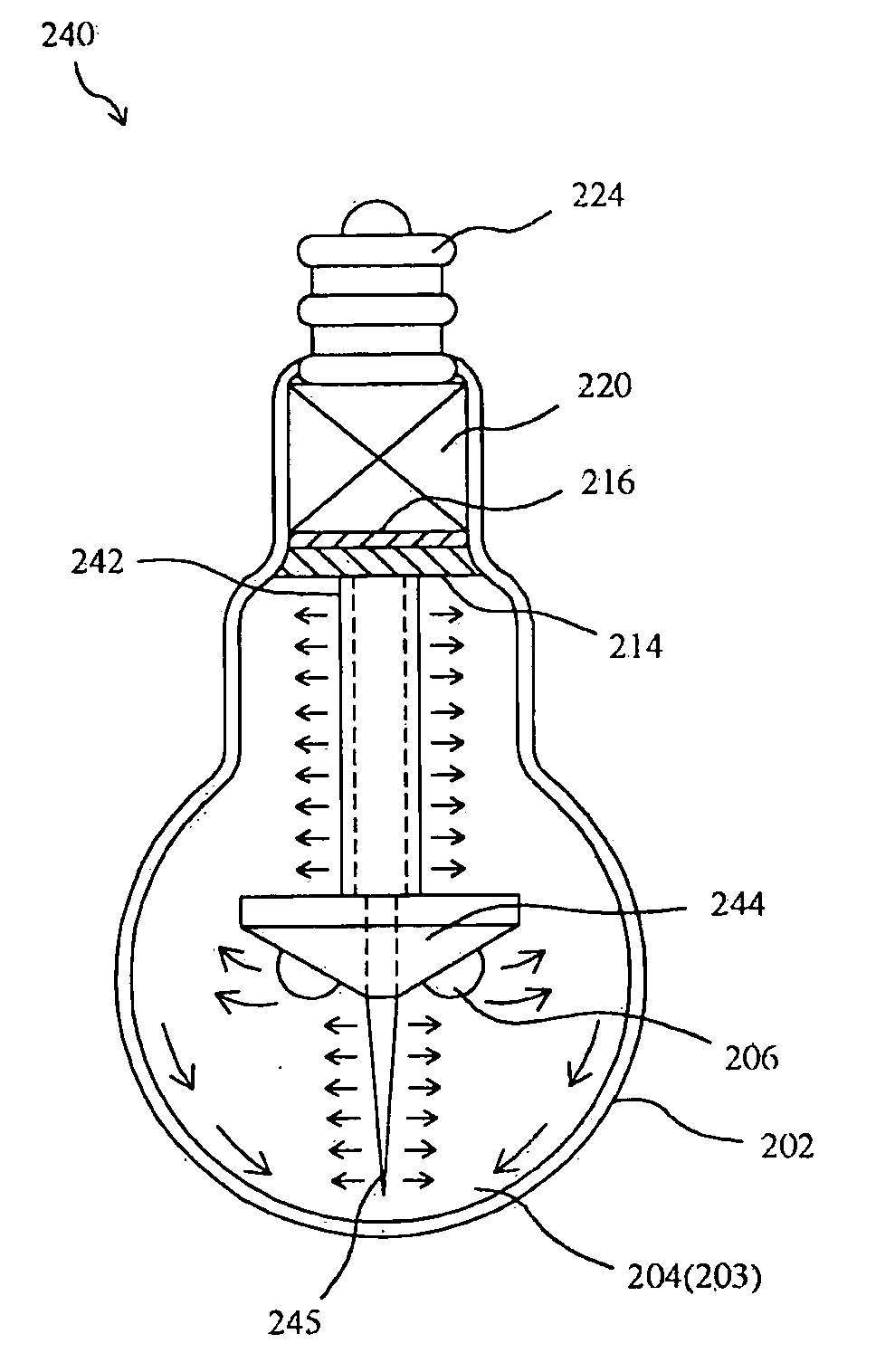
[0041]FIG. 13 shows a high power LED lamp 200 according to the present invention, and FIG. 14 is a decomposition diagram. In the high power LED lamp 200, container 202 has a cavity 203 to fill with transparent or translucent liquid 204, light source module includes high power LED package 206 consuming power of for example more than 0.3 W, mounted on metal core printed circuit board 210 having power lines 222 therefrom, package resin 208 fixes the high power LED package 206 and the metal core printed circuit board 210 on carrier 212 and provides water sealing function, axial fins assembly 211 is installed in front of the high power LED package 206 and thermally connected to the carrier 212, axial thermally conductive tube 213 has one end inserted into positioning ring 214 and water sealing cap 216 and the other end thermally connected to the carrier 212 too, sealing material 218 on the sealing cap 216 seals the aperture of the container 202, and power conversion and driving module 22...


PUM

PropertyMeasurementUnit
air temperatureaaaaaaaaaa
temperatureaaaaaaaaaa

Abstract

A high power LED lamp comprises a container having a cavity to fill with a liquid, a light source module for providing a high power LED source light to penetrate through the liquid, and an axial thermal conductor having a first portion nearby the light source module and a second portion extending in the liquid along an axial direction of the cavity to far away from the light source module to evenly transfer heat from the light source module through the liquid to the container.

Description

FIELD OF THE INVENTION[0001]The present invention is related generally to a lamp and, more particularly, to a high power light-emitting diode (LED) lamp for illumination purpose.BACKGROUND OF THE INVENTION[0002]Due to its long lifetime, power saving and environment protection, LED has been widely used in decorative lamps such as underwater lights and indicative lamps such as traffic lights. However, it is still not suitable for illumination purpose since the brightness per unit power consumption it generates is not high enough, the heat dissipation it is provided with is not efficient enough, and the emission angle of lights it radiates is not wide enough. Along with the improvement of white LED, the brightness per unit power consumption is gradually enhanced. Recently, for example, it is commercialized of white LED brighter than traditional incandescent bulb, which is up to 30 μm / W, and it is also expected in a few days the commercialization of white LED brighter than fluorescent t...

Claims


Application Information

Patent Timeline
Patent Type & Authority Applications(United States)
IPC IPC(8): F21V29/00F21K99/00
CPCF21Y2101/02F21S8/086F21K9/137F21V3/0418F21V3/0436H01L2224/45144F21K9/135F21V29/773F21V29/58F21V29/006H01L2224/48091H01L2224/48247H01L2224/49109H01L2924/00014H01L2924/00F21V29/67F21K9/232F21K9/233F21Y2115/10F21V3/061F21V3/062F21V29/51F21V29/75
Inventor CHIANG, KUN-YUAN
Owner LIQUIDLEDS LIGHTING
Why Eureka
Try Eureka