Energy efficient building

a building energy and building technology, applied in the field of building energy systems, can solve the problems of low energy efficiency, negative pressure in the core, and high internal load in the lower portion of the building, and achieve the effect of no energy costs, no energy costs, and improved building energy efficiency

Inactive Publication Date: 2009-11-05
SKIDMORE OWINGS & MERRILL LLP
View PDF27 Cites 10 Cited by
  • Summary
  • Abstract
  • Description
  • Claims
  • Application Information

AI Technical Summary

Benefits of technology

[0003]Methods and systems consistent with the present invention improve building energy efficiency. A solar engine, which is vertically aligned along an interior portion of a building, is heated by solar radiation. The solar engine includes a warm air chamber at an upper portion of the solar engine and a hollow core or void positioned below the warm air chamber. Habitable spaces are positioned around the outside of the core toward an exterior of the building. Solar radiation on the warm air chamber creates a high temperature zone in the warm air chamber. This creates a stack effect in which air rises through the core due to the lower temperatures in the core, and results in a negative pressure in the core. Air enters at a lower portion of the building and is pulled through the core by the solar engine. If the windows on the outside of the habitable spaces are opened, the negative pressure in the core causes passive cross ventilation from the outside of the building through the habitable spaces and into the core, where the air rises to the warm air chamber and then out of the building. This allows the habitable spaces to be naturally cooled and ventilated with no energy costs.

Problems solved by technology

This creates a stack effect in which air rises through the core due to the lower temperatures in the core, and results in a negative pressure in the core.
Habitable spaces in a lower portion of the building may generate high internal loads and may require cooling in the interior zones.
The preconditioning of the air by drawing it through the core as opposed to the exterior of the building saves considerable heating energy.
Further, air from the core provides more consistent ventilation compared to air brought in through louvers located outside the building, which are susceptible to changing wind conditions and often cannot pull in air since the suction forces of the wind may outweigh the external static pressure of the louver fan.

Method used


Image

  • Energy efficient building
  • Energy efficient building
  • Energy efficient building

Examples


Embodiment Construction

[0024]Reference will now be made in detail to an implementation consistent with the present invention as illustrated in the accompanying drawings. Wherever possible, the same reference numbers will be used throughout the drawings and the following description to refer to the same or like parts.

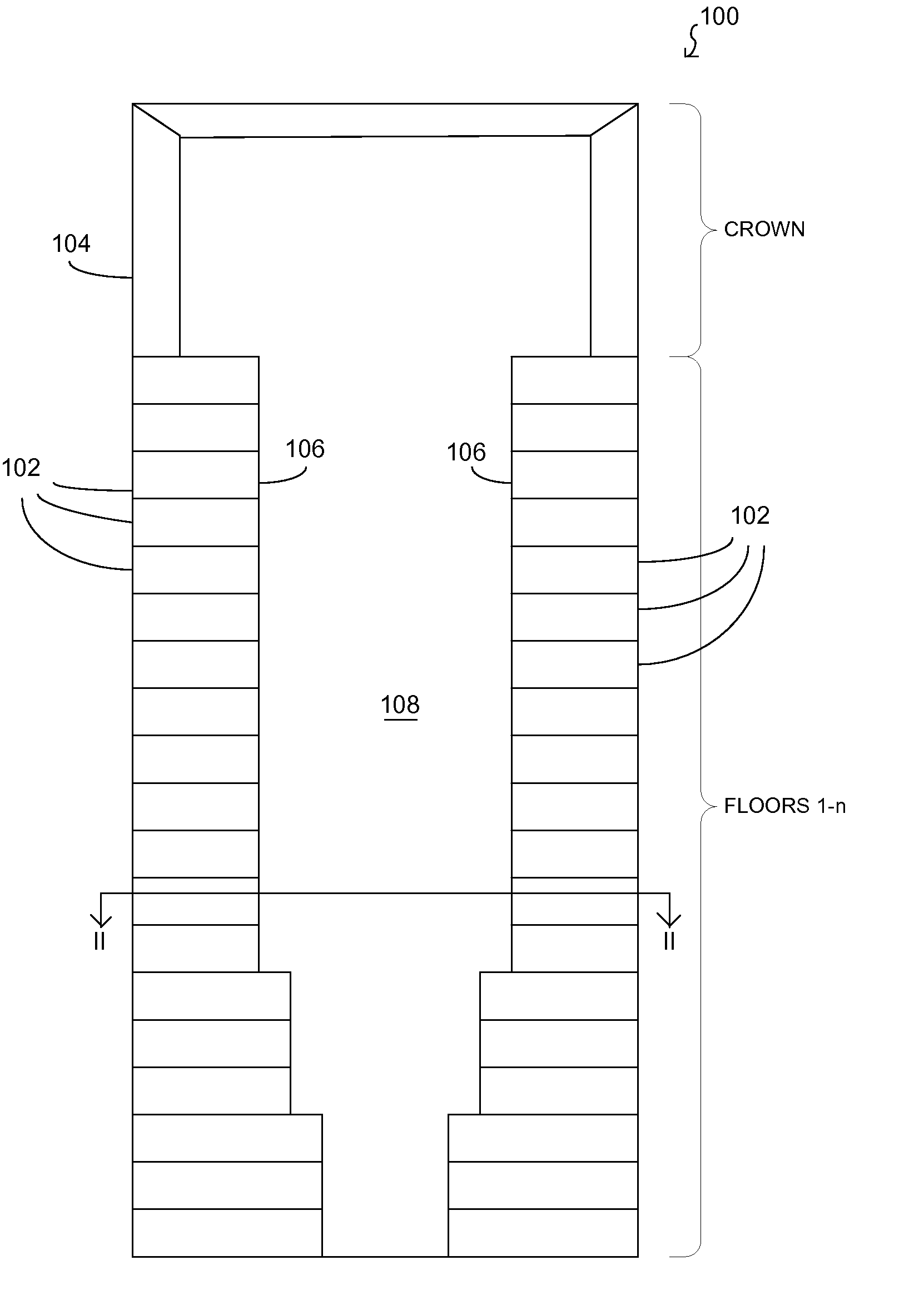
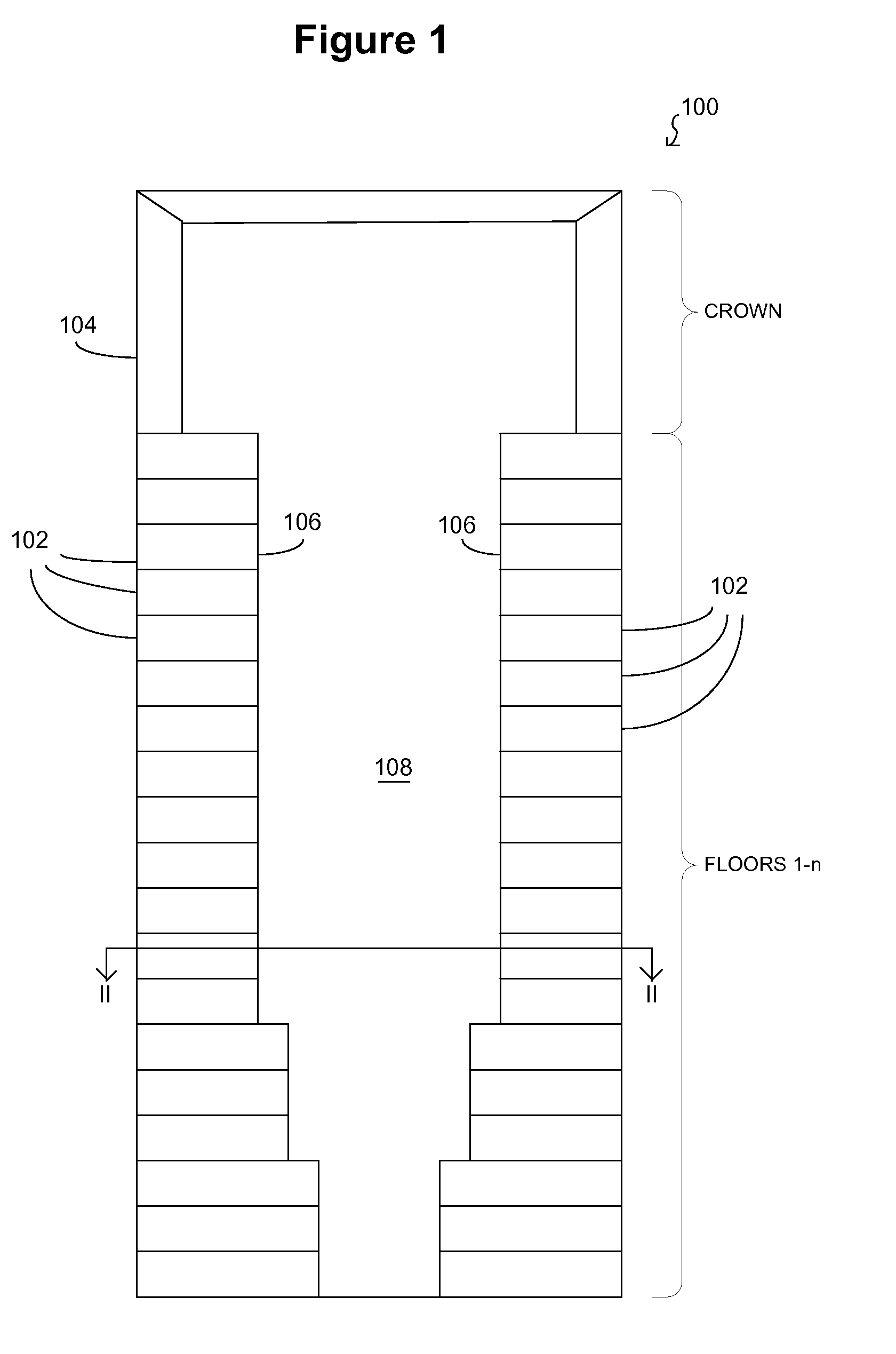
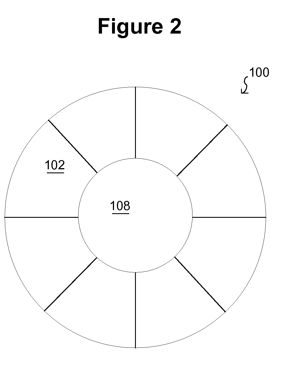
[0025]Methods and systems consistent with the present invention improve building energy efficiency. FIG. 1 is a vertical cross-sectional view of an illustrative building 100 consistent with the present invention. The illustrative building comprises a plurality of floors 1-n of habitable spaces 102 in a lower portion of the building and a crown 104 at an upper portion of the building. The habitable spaces 102 are positioned around an exterior portion of the building. The interior walls 106 of the habitable spaces 102 form the outer boundary of a core 108 or open space at an interior portion of the building. In the illustrative example, the core is an atrium that extends the height of the habita...


PUM


Abstract

A solar engine, which is vertically aligned along an interior portion of a building, is heated by solar radiation. The solar engine includes a warm air chamber at an upper portion of the solar engine and a hollow core positioned below the warm air chamber. Habitable spaces are positioned around the outside of the core toward an exterior of the building. Solar radiation on the warm air chamber creates a high temperature zone in the warm air chamber that induces a stack effect in which air rises through the core due to the lower temperatures in the core, and results in a negative pressure in the core. Air enters at a lower portion of the building and is pulled through the core by the solar engine. If the windows on the outside of the habitable spaces are opened, the negative pressure in the core causes passive cross ventilation from the outside of the building through the habitable spaces and into the core, where the air rises to the warm air chamber and then out of the building. This allows the habitable spaces to be naturally cooled and ventilated with no energy costs. Solar radiation may be directed into the warm air chamber and core using a reflector at the top of the building. One or more wind turbines and generators positioned around the top of the core convert the moving air from the core into electrical energy to power the building.

Description

FIELD OF THE INVENTION[0001]The present invention generally relates to building energy systems, and more particularly to controlling ventilation and temperature and generating power in buildings using the stack effect.BACKGROUND OF THE INVENTION[0002]Conventional building designs rely on powered building-mechanical systems to bring ventilation into habitable spaces from the outside of the building. These conventional designs typically include powered louvers positioned on the outer surfaces of the building that open to allow air to enter the habitable spaces for ventilation, heating, and cooling. Typically, powered fans draw the outside air through the louvers and into the habitable spaces, and then expel the air from the habitable spaces to the outside of the building. This conventional approach requires large energy consumption to drive the louvers and power the fans. A need exists for improved energy efficiency in buildings.SUMMARY OF THE INVENTION[0003]Methods and systems consis...

Claims


Application Information

Patent Timeline
Patent Type & Authority Applications(United States)
IPC IPC(8): F24F7/00
CPCF03G6/045F05B2240/911F24F5/0075F24F2005/0064F24J2/0444Y02B10/24Y02B10/30Y02B30/92Y02E10/465Y02B10/70Y02B10/20F24S20/66Y02B30/90Y02E10/46Y02A30/00Y02A30/272
Inventor HOLT, NICHOLASCOOPER, CHRISTOPHER B.FRECHETTE, III, ROGER EUGENEBAKER, JR., WILLIAM F.
Owner SKIDMORE OWINGS & MERRILL LLP
Why Eureka
Try Eureka