Polar Modulator and Method for Generating a Polar-Modulated Signal

a modulator and signal technology, applied in the field of polar modulators, can solve the problems of increasing error performance, generating unwanted am/fm signal components, and significant deterioration of the modulation spectrum

Active Publication Date: 2009-11-05
INTEL CORP
View PDF7 Cites 14 Cited by
  • Summary
  • Abstract
  • Description
  • Claims
  • Application Information

AI Technical Summary

Benefits of technology

[0008]A polar modulator for generating a polar-modulated signal based on amplitude information and phase information includes, for example, a phase-locked loop for setting a frequency depending on a control value in order to obtain a phase-locked loop output signal. The polar modulator further includes a modulation means for combining an amplitude signal derived from the amplitude information with the phase-locked loop output signal in order to generate the polar-modulated signal. The polar modulator further includes a control value generator which is implemented to generate the control value based on the amplitude information and phase information, the control value generator being implemented to additively overlay a signal value derived from the amplitude information and a signal value corresponding to the phase information or a signal value derived from the phase information in order to generate the control value.

Problems solved by technology

For EDGE systems, however, the coupling of the output signal into the voltage-controlled oscillator (VCO) of the phase-locked loop (PLL) sometimes causes the generation of unwanted AM / FM signal components (AM=amplitude modulation, FM=frequency modulation) which become noticeable with an interference of the FM signal at the output of the VCO.
The unwanted AM / FM signal components lead to a significant deterioration of the modulation spectrum and increase error performance.

Method used


Image

  • Polar Modulator and Method for Generating a Polar-Modulated Signal
  • Polar Modulator and Method for Generating a Polar-Modulated Signal
  • Polar Modulator and Method for Generating a Polar-Modulated Signal

Examples


Embodiment Construction

[0023]In the following, with reference to the accompanying FIGS. 1 to 9, embodiments of a polar modulator and a method for generating a polar-modulated signal are now illustrated in detail.

[0024]With reference to the following description of the embodiments according to the invention, it should be noted that, in the description and in the different figures, the same reference numerals are used for functionally identical or seemingly identical or equivalent elements for reasons of clarity.

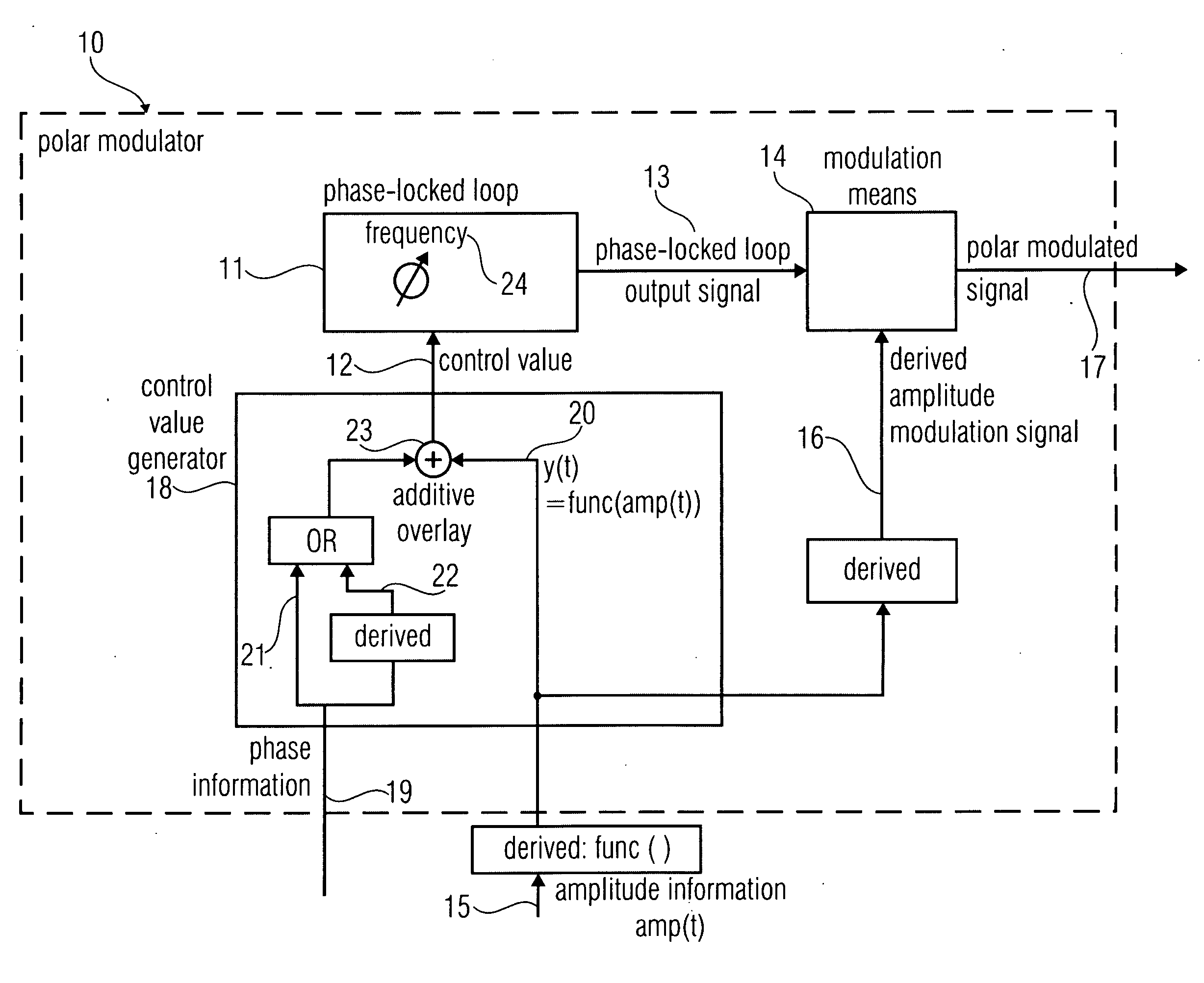
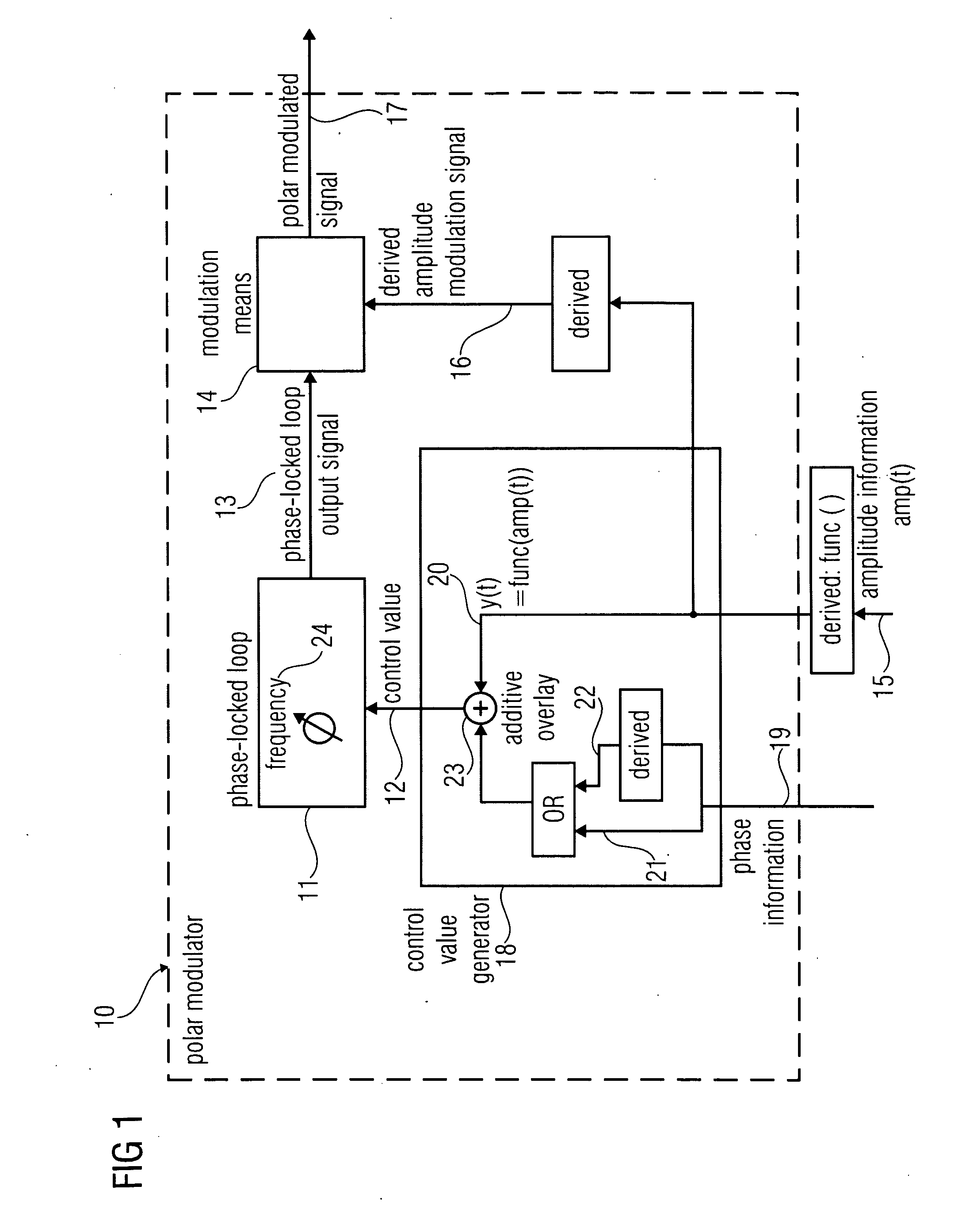
[0025]FIG. 1 shows a block diagram of a polar modulator according to an embodiment of the invention. The polar modulator 10 generates a polar-modulated signal 17 based on amplitude information 15 and phase information 19. The polar modulator 10 includes a phase-locked loop 11 for setting a frequency 24 depending on a control value 12 to obtain a phase-locked loop output signal 13. The polar modulator 10 further includes a modulation means 14 for combining an amplitude signal 16 derived from the ampl...


PUM


Abstract

A polar modulator for generating a polar-modulated signal based on amplitude information and phase information includes a phase-locked loop which is implemented to enable a setting of a frequency depending on a control value to obtain a phase-locked loop output signal. The polar modulator further includes a modulation means which is implemented to combine an amplitude modulation signal derived from the amplitude information with the phase-locked loop output signal to generate the polar-modulated signal. The polar modulator further includes a control value generator which is implemented to high-pass filter an amplitude signal derived from the amplitude information, to obtain a high-pass filtered amplitude signal, wherein the control value generator is implemented to combine the high-pass filtered amplitude signal with a phase signal based on the phase information to generate the control value signal representing the control value.

Description

CROSS-REFERENCE TO RELATED APPLICATIONS[0001]This application claims priority from German Patent Application No. 102008021876.6-31, which was filed on May 2nd, 2008, and is incorporated herein in its entirety by reference.BACKGROUND OF THE INVENTION[0002]Embodiments according to the invention relate to a polar modulator.[0003]Some embodiments according to the invention relate to a polar modulator which may be used in mobile radio telephones which use modulation methods with a non-constant envelope for increasing the data rate, for example according to the mobile radio standard GSM-EDGE (GSM=global system for mobile communication; EDGE=enhanced data rate for GSM evolution).[0004]With the rapidly progressing development on the mobile radio market, the development of power-efficient wireless transmit / receive architectures has become an important point for the design of portable mobile devices. Mobile radio telephones of the next generation which utilize the GSM-EDGE standard for exampl...

Claims


Application Information

Patent Timeline
Patent Type & Authority Applications(United States)
IPC IPC(8): H04M1/00H04L27/20
CPCH04L27/368H04L27/361
Inventor PUMA, GIUSEPPE LIFELTGEN, MICHAEL
Owner INTEL CORP
Why Eureka
Try Eureka