
Hybrid polar modulator differential phase Cartesian feedback correction circuit for power amplifier linearization

a technology of power amplifiers and feedback correction circuits, applied in amplifier modifications to reduce non-linear distortion, digital transmission, baseband system details, etc., can solve problems such as modulation distortion, modulation distortion, non-linear distortion, etc., and achieve accurate estimates of phase and amplitude distortions

Active Publication Date: 2008-08-05
APPLE INC
View PDF28 Cites 24 Cited by
  • Summary
  • Abstract
  • Description
  • Claims
  • Application Information

AI Technical Summary

Benefits of technology

[0010]The present invention, generally speaking, provides a method of obtaining very accurate estimates of the phase and amplitude distortions introduced by radio frequency or microwave power amplifiers even where polar modulation is used.

Problems solved by technology

Ideally, these DC supply voltage variations would transfer perfectly to the RF envelope, but in practice the conversion is impaired by non-linear effects, characterized as AM-to-AM (amplitude modulation) distortions and AM-to-PM (phase modulation) distortions.
Both these types of errors degrade the power spectral density and the EVM (error vector magnitude) of the desired signal.
The accuracy of commonly-used power detectors is inadequate for the precision needed to prevent significant distortions to the spectrum and EVM.
Unfortunately, the reference for the in-phase and quadrature mixers of a Cartesian feedback detector is not readily available in a polar-modulation-based transmitter.
At this point the signal has already been impaired by distortions in the amplifier.
However, new signals represent a potential for the creation of even more non-linear distortion.
Furthermore, in frequency-hopping applications, it would be necessary to hop these references also, adding substantial complexity.
Moreover, even if such a reference signal were created, it would still not allow for correction of impairments in the power amplifier.

Method used


Image

  • Hybrid polar modulator differential phase Cartesian feedback correction circuit for power amplifier linearization
  • Hybrid polar modulator differential phase Cartesian feedback correction circuit for power amplifier linearization
  • Hybrid polar modulator differential phase Cartesian feedback correction circuit for power amplifier linearization

Examples


Embodiment Construction

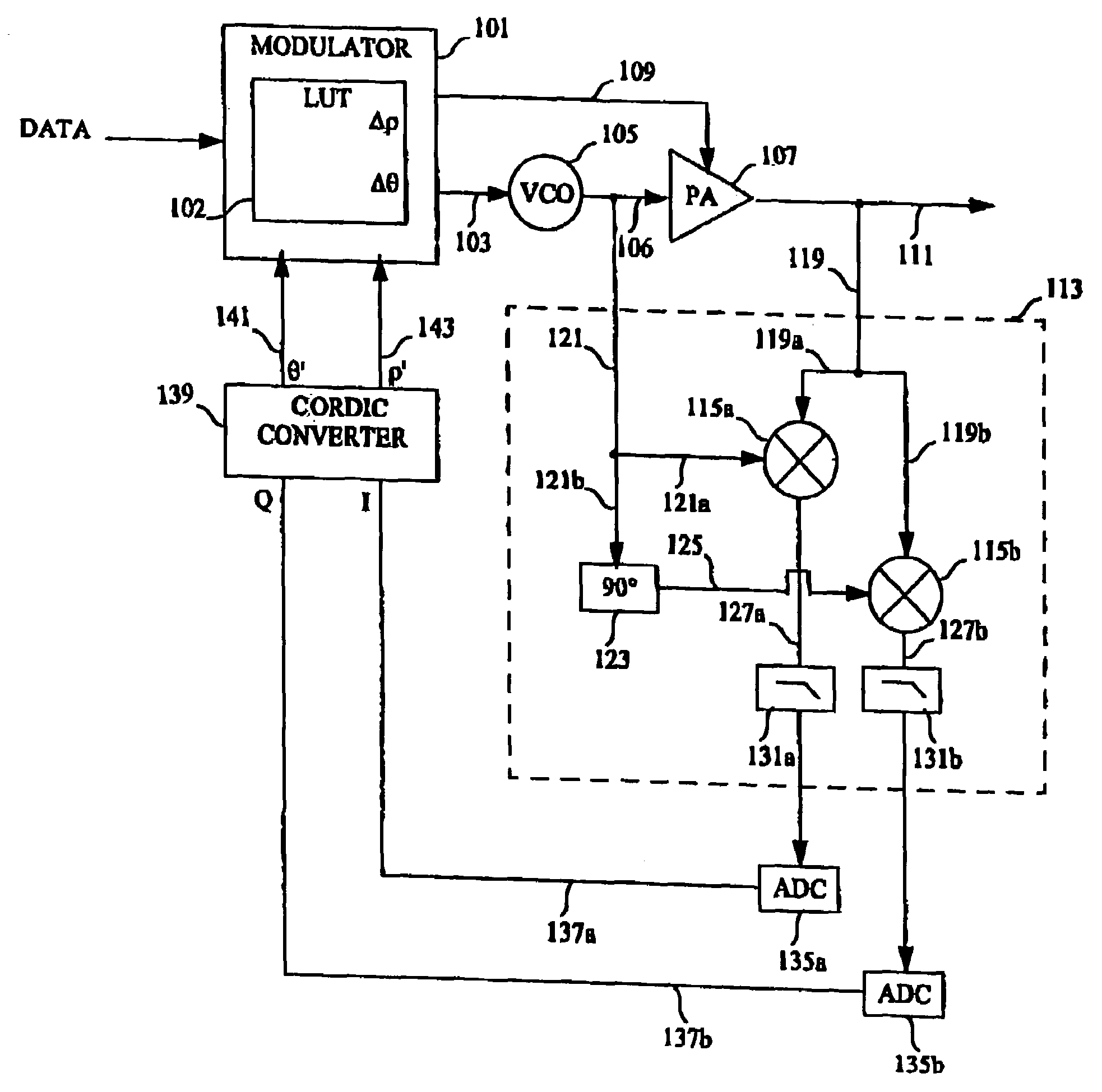
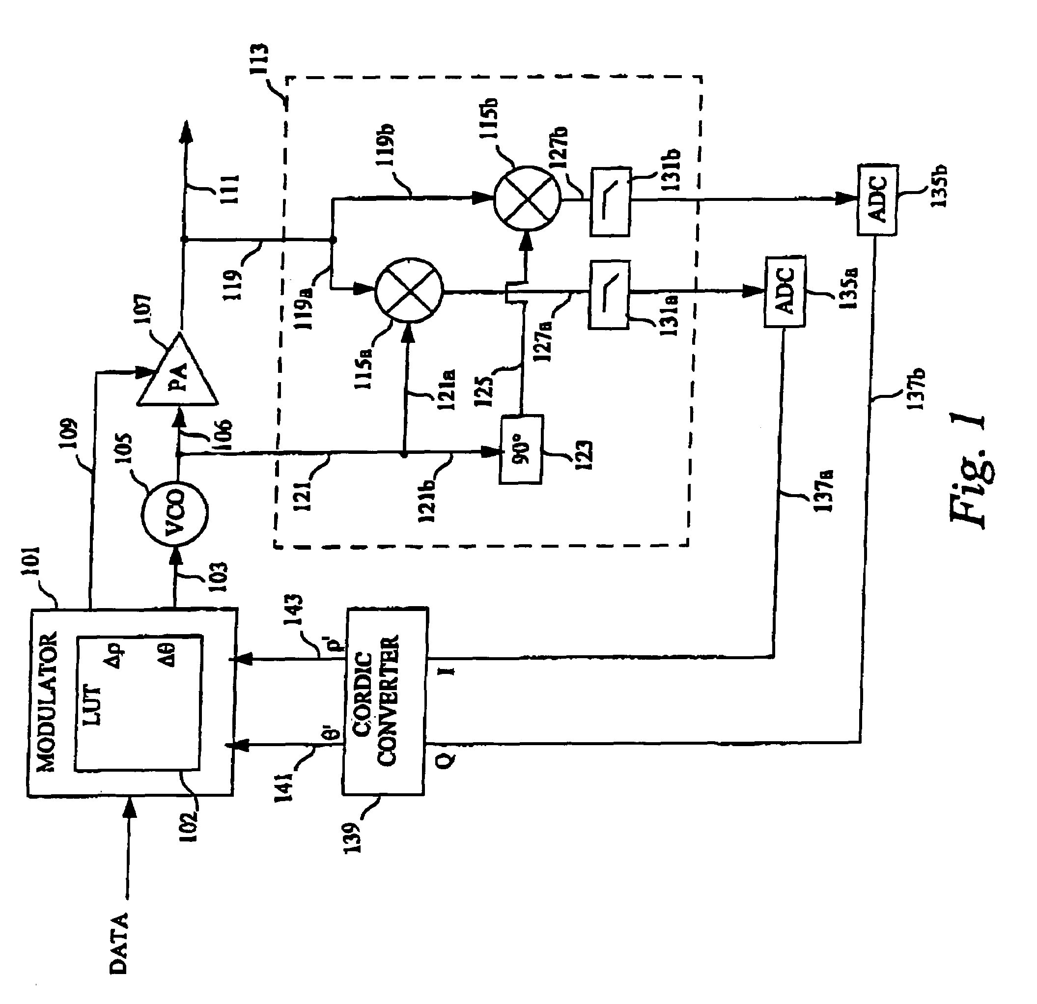
[0016]Referring now to FIG. 1, a diagram is shown of a linearization feedback circuit in accordance with an exemplary embodiment of the invention. A modulator 101 receives data and in response produces phase and amplitude control signals used to generate an RF signal representing the data. In the illustrated embodiment, the modulator 101 includes a correction table 102 used to store delta-phase and delta-amplitude values for various amplitude levels. These values are used to adjust the phase and amplitude control signals to compensate for distortion of the amplifier.

[0017]The phase control signal 103 is input to a voltage controlled oscillator (VCO) 105 that produces a low-level RF output signal of the desired phase. The output signal of the VCO forms an input signal 106 for input to the amplifier and is applied to an amplifier chain including one or more amplifier stages. The amplifier chain is represented in FIG. 1 by an amplifier 107.

[0018]The amplitude control signal 109 produce...


PUM


Abstract

The present invention, generally speaking, provides a method of obtaining very accurate estimates of the phase and amplitude distortions introduced by radio frequency or microwave power amplifiers even where polar modulation is used.

Description

BACKGROUND[0001]1. Field of the Invention[0002]The present invention relates to feedback correction for power amplifier linearization.[0003]2. Description of Related Art[0004]There are many methods for extending the upper limit of the power range of an amplifier. These are all intended to compensate for the more-or-less non-linear nature of the amplifier, particularly as the voltage waveform nears the upper and lower limits of the physically-achievable voltage range. Linearity compensation methods fall into two general categories: feed forward and feedback linearization. The methods discussed herein are of the feedback type.[0005]There are two general types of feedback methods for linearization of RF or microwave power amplifiers, namely polar and Cartesian. The polar method of feedback correction compares both the output phase and amplitude to the input phase and amplitude of the amplifier and adjusts (predistorts) the input to account for the distortions introduced by the amplifie...

Claims


Application Information

Patent Timeline
Patent Type & Authority Patents(United States)
IPC IPC(8): H04L27/00H03F1/32H04L27/36
CPCH03F1/3294H04L27/368H03F2200/57H03F2201/3233H03F2201/3224
Inventor BOOTH, RICHARD W. D.TWITCHELL, EDWIN R.MOW, MATTHEW A.
Owner APPLE INC
Learn More