Eureka AIR delivers breakthrough ideas for toughest innovation challenges, trusted by R&D personnel around the world.

System and Method for Lasers in Surgical Applications

a laser and surgical technology, applied in the field of non-co2 laser generators, can solve the problems of large and cumbersome dimensions of cosub>2 /sub>lasers, constraining the use of cosub, and surgical operations can be accomplished with heretofore unrealized, so as to avoid challenges and difficulties, and facilitate surgical use

Active Publication Date: 2009-11-05
LUMENIS LTD
View PDF1 Cites 20 Cited by
  • Summary
  • Abstract
  • Description
  • Claims
  • Application Information

AI Technical Summary

Benefits of technology

The patent describes a new laser system that can achieve the same water absorption levels as a CO2 laser without using a CO2 laser. This system has the benefits of a CO2 laser but without the difficulties and limitations of using one. The laser system includes a laser generator that generates laser radiation to cause water absorption levels that approximate those of a CO2 laser. The system includes one or more fibers to deliver the laser radiation to a target. The laser generator includes a laser diode or multiple diode arrays that generate wavelengths in the range of 2.4 μm to 2.75 μm. The system can be used in surgical procedures for inside-the-body applications. The technical effects of this patent are improved laser systems that can achieve the same water absorption levels as a CO2 laser without using a CO2 laser.

Problems solved by technology

By achieving the approximate absorption levels of water of those produced by CO2 lasers without using a CO2 laser, surgical operations can be accomplished with heretofore unrealized results.
One drawback is the large and cumbersome dimensions of CO2 lasers due to the size of CO2 laser tubes.
Another drawback is the long wavelength of the radiation produced by CO2-type laser generators that makes it difficult to use fiber delivery devices / instruments (e.g., optical fibers) to couple and / or guide radiation produced by CO2 laser generators to a target location, thus constraining the use of CO2 laser generators with, for example, flexible endoscopes and bronchoscopes (which are configured to receive fiber delivery devices) to perform surgical applications in the interior of patients' bodies.
Another drawback of the CO2 laser is its relatively large spot size resulting from the large diffraction limit associated with the long wavelength of the radiation produced by such laser systems.

Method used


Image

  • System and Method for Lasers in Surgical Applications
  • System and Method for Lasers in Surgical Applications
  • System and Method for Lasers in Surgical Applications

Examples


Embodiment Construction

[0043]The following disclosure described with reference to the drawings is illustrative of the systems, devices and methods and is not intended to limit the embodiments of the systems and methods encompassed by the claims of this application.

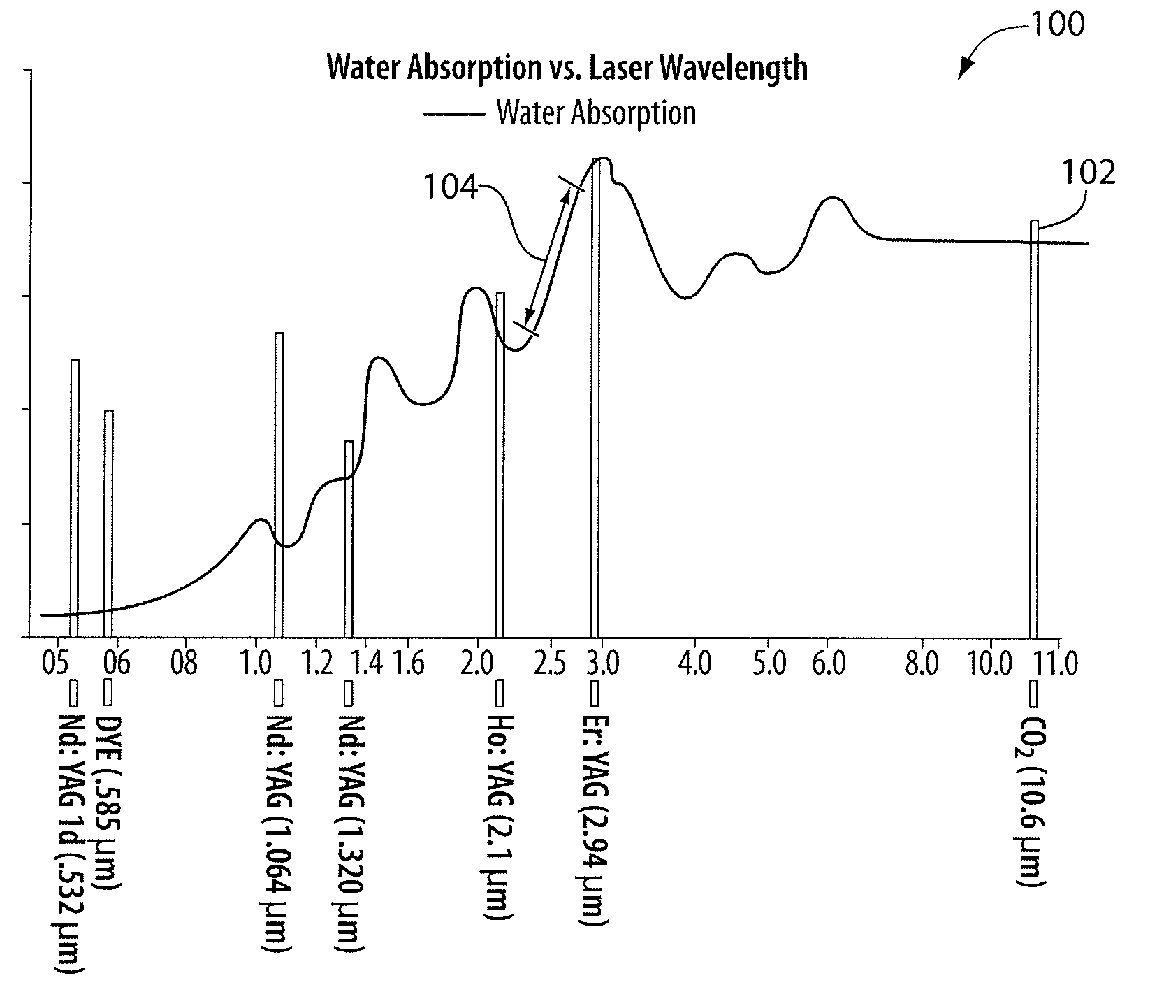
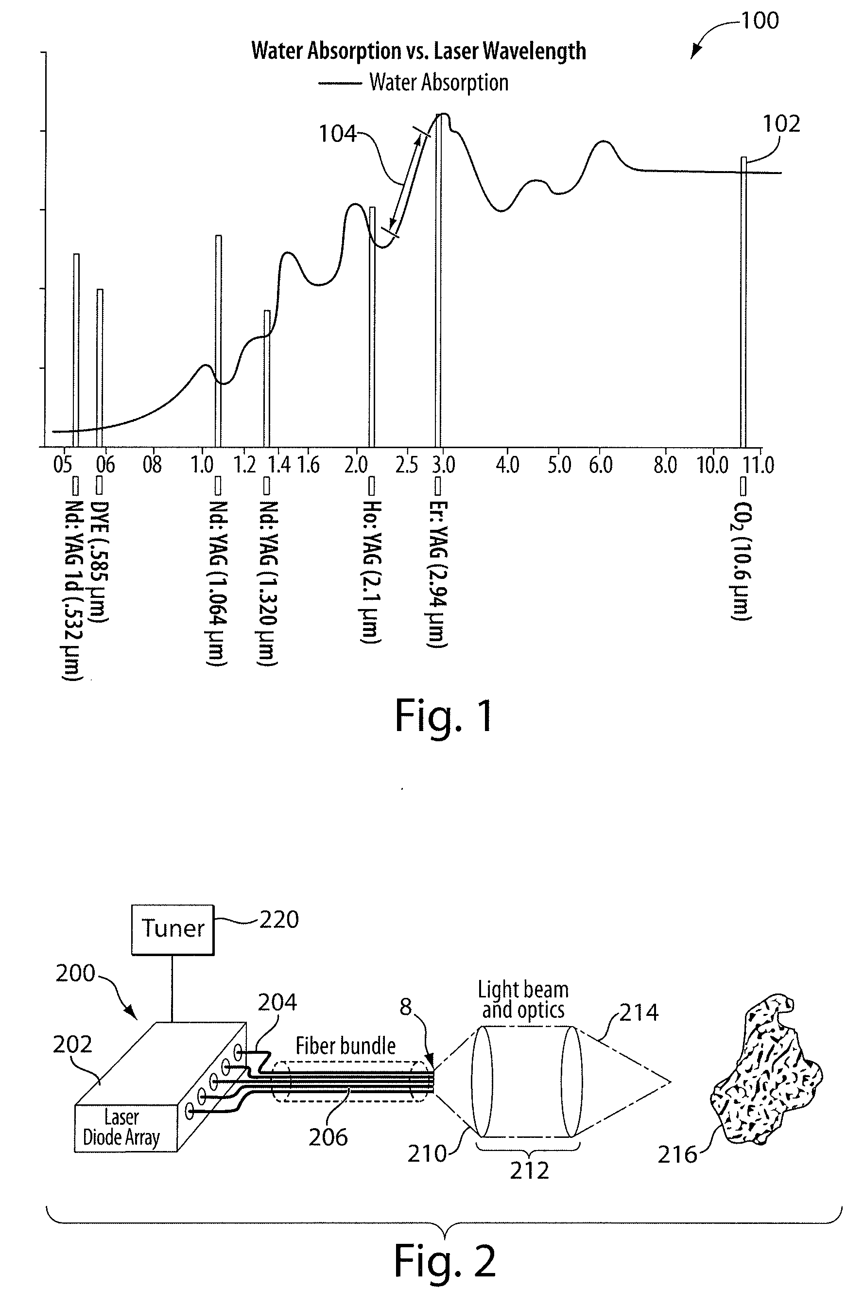
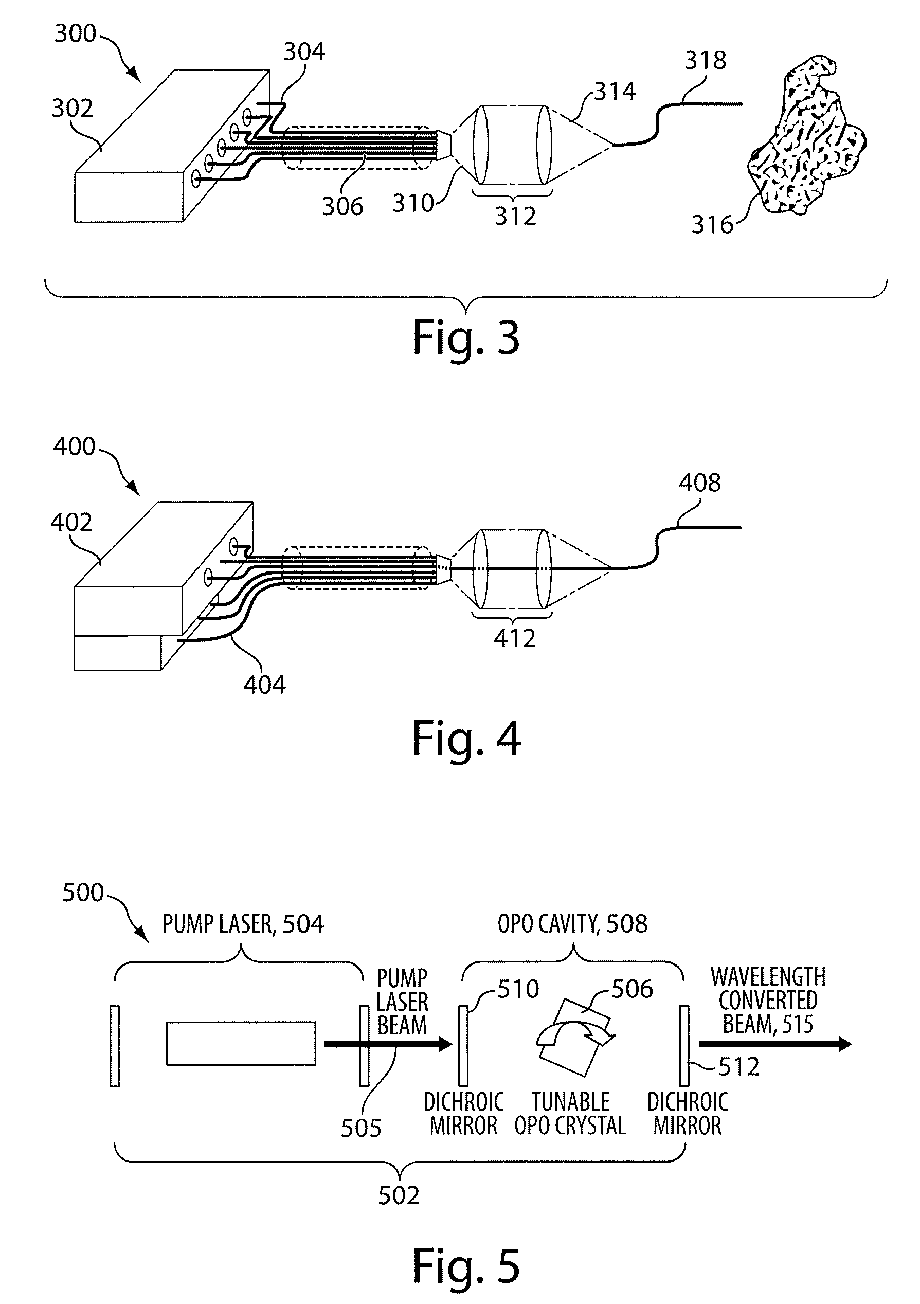
[0044]Disclosed herein are systems, devices and methods to generate laser radiation that can cause water absorption levels (when applied to a target) that approximate water absorption levels achieved with a CO2 laser. The disclosed systems, devices and methods are implemented and / or practiced without using a CO2 laser. In some embodiments, a surgical laser system that includes a laser generator (e.g., a laser generator implemented using at least one quantum-well laser diode, a laser generator implemented using a pump-laser device, etc.) to generate laser radiation to cause water absorption levels that approximate water absorption levels achieved with a CO2 laser is disclosed. Coupled to the laser generator are one or more fibers to deliver the g...


PUM


Abstract

Disclosed is a surgical laser system. The system includes a laser generator to generate laser radiation to cause water absorption levels that approximate water absorption levels achieved with a CO2 laser, and one or more fibers coupled to the laser generator to deliver the generated laser radiation. In some embodiments, the laser generator is configured to generate radiation at multiple possible wavelengths in a range of between about 2.4 μm to about 2.75 μm.

Description

CROSS-REFERENCE TO RELATED APPLICATIONS[0001]This application claims priority to provisional U.S. application Ser. No. 61 / 063,340, entitled “Device and Method for Lasers in Surgical Applications,” filed Feb. 1, 2008, the content of which is hereby incorporated by reference in its entirety.BACKGROUND OF THE INVENTION[0002]The present disclosure generally relates to a laser for surgical applications. More particularly, the present disclosure relates to non-CO2 laser generators (e.g., non-CO2 laser devices, implemented, for example, based on quantum-well diode arrays) that achieve approximately the same water absorption levels typically produced by a CO2 laser. By achieving the approximate absorption levels of water of those produced by CO2 lasers without using a CO2 laser, surgical operations can be accomplished with heretofore unrealized results.[0003]The CO2 laser was described by Patel et al. (see, for example, C. K. N. Patel, W. L. Faust and R. A. McFarlane, “CW Laser Action on Ro...

Claims


Application Information

Patent Timeline
Patent Type & Authority Applications(United States)
IPC IPC(8): A61B18/22
CPCH01S3/00A61B18/22H01S3/2232A61B2018/00571
Inventor FEIN, ASAGOLDRING, ALON
Owner LUMENIS LTD
Why Eureka
Eureka Blog
Learn More