
Aircraft brake control system and method

a control system and aircraft technology, applied in aircraft braking arrangements, process and machine control, instruments, etc., can solve the problems of uncontrolled braking due to failure, increase cost and weight, and aircraft can not adequately protect, so as to facilitate the application of a second braking force and facilitate the first braking force

Inactive Publication Date: 2009-11-05
THE BF GOODRICH CO
View PDF3 Cites 71 Cited by
  • Summary
  • Abstract
  • Description
  • Claims
  • Application Information

AI Technical Summary

Benefits of technology

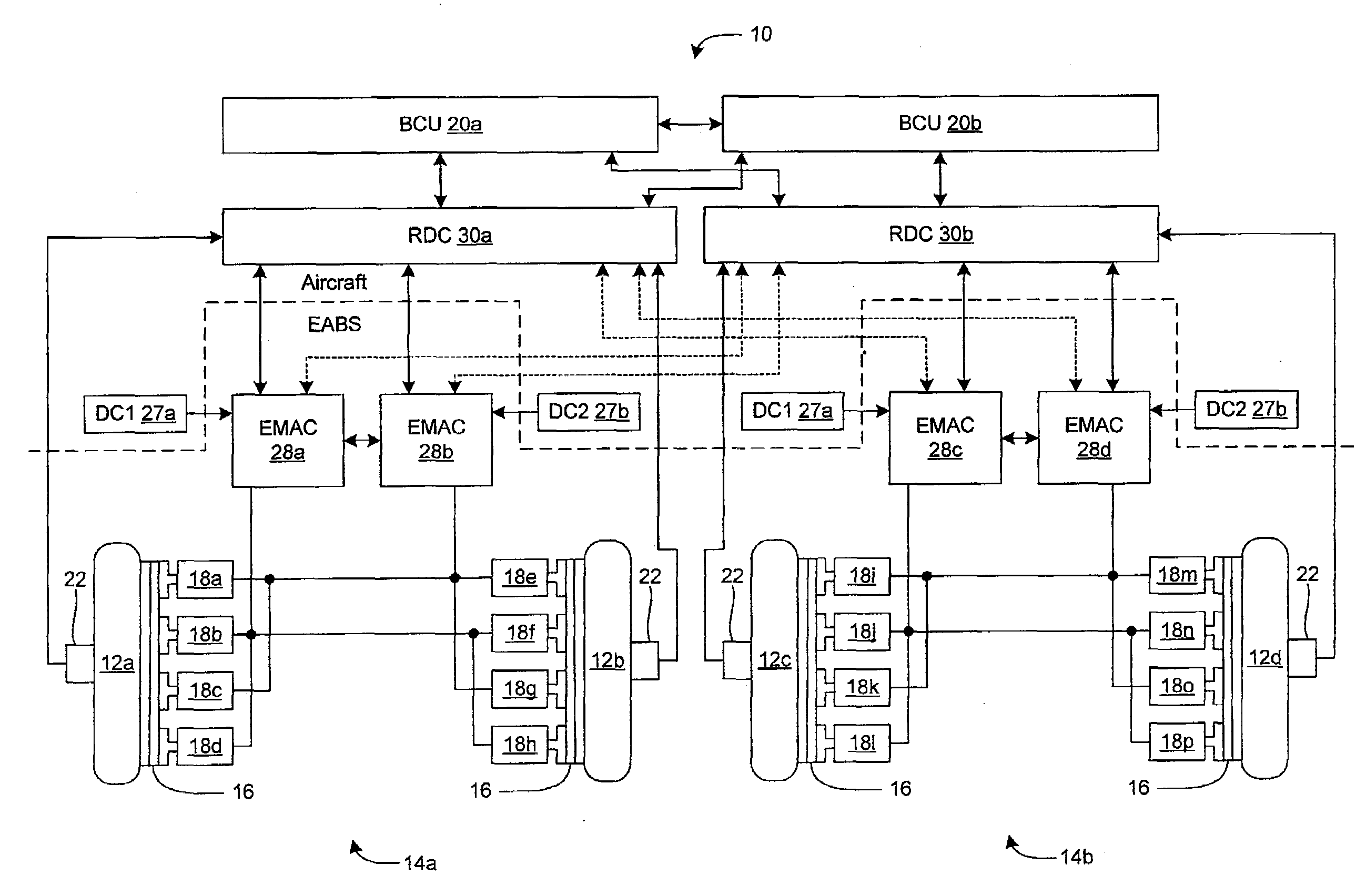
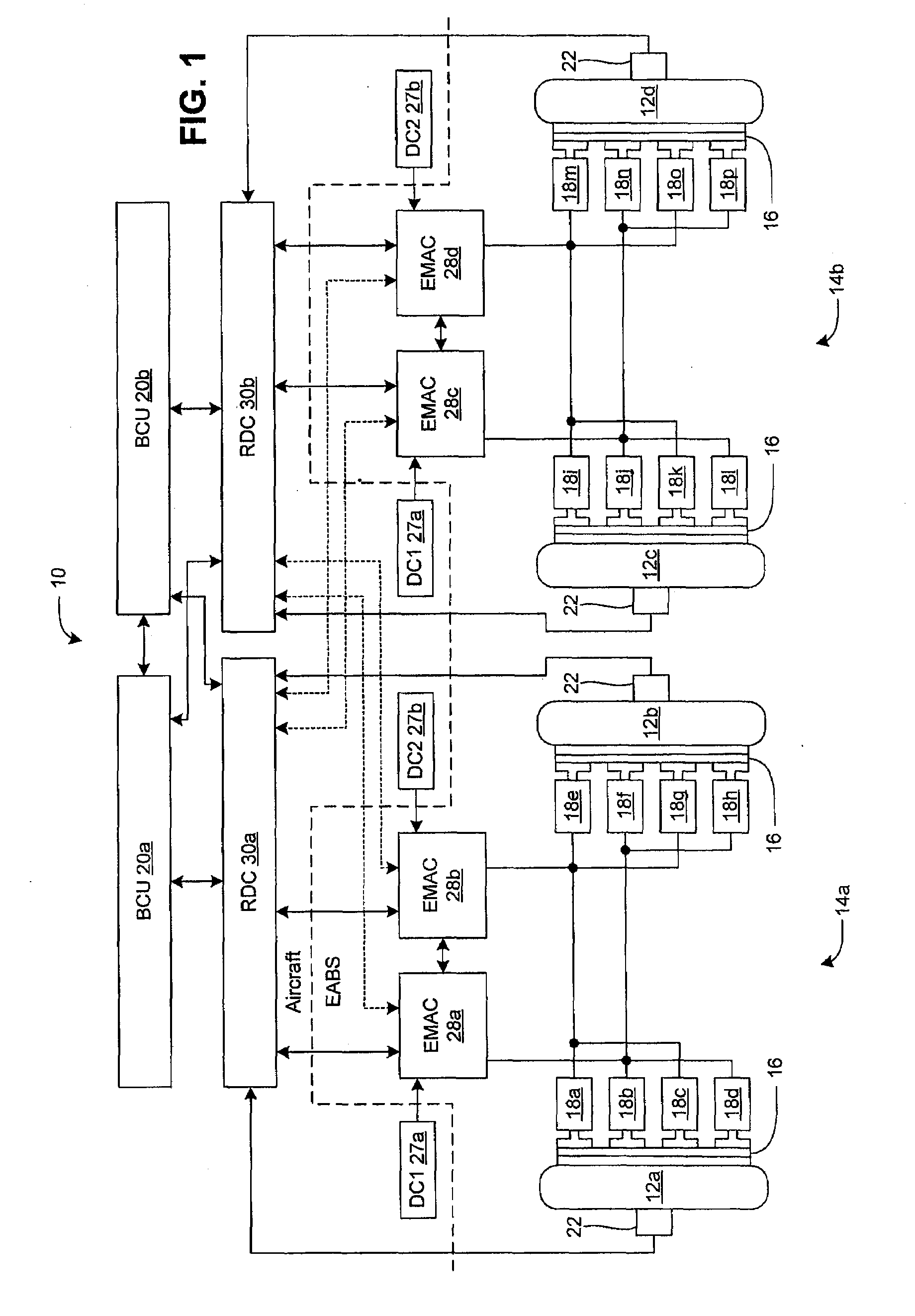
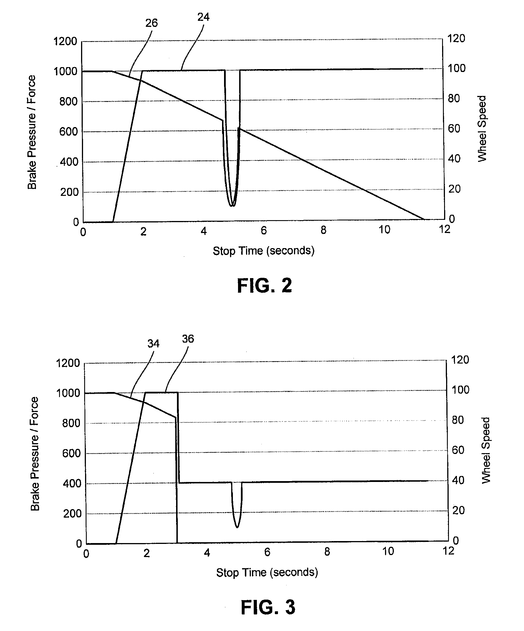
[0009]A method according to an embodiment includes receiving an input brake command that indicates a desired amount of braking for a vehicle. A brake control signal is then derived from the input brake command to facilitate applying a braking force to a wheel of the vehicle, and the braking force facilitates achieving the desired amount of braking for the vehicle. The method further comprises determining whether data from a sensor associated with the wheel is unavailable, and then modifying the brake control signal to that wheel in response to a determination that the data is unavailable. Such modification facilitates the desired amount of braking for the vehicle.
[0013]The BCU may be configured to derive a second brake control signal from the input brake command to facilitate applying a second braking force to a second wheel of the vehicle in accordance with various embodiments. A first brake control signal is associated with a first wheel of the vehicle and may be configured to facilitate applying a first braking force to the first wheel. A first sensor may be configured to provide first data associated with the first wheel. The first braking force and the second braking force may together facilitate achieving the desired amount of braking for the vehicle.
[0015]In an embodiment, the second data may be substituted for the first data in response to the first data being unavailable, and the second data may be used to determine the first brake control signal. In various embodiments, the second data may be used to generate the second brake control signal, and modifying the first brake control signal may include replacing the first brake control signal with the second brake control signal in response to the first data from the first sensor being unavailable. In an embodiment, modifying the brake control signal may include periodically pulsing the braking force to facilitate avoiding a skid condition of the wheel.

Problems solved by technology

An aircraft often presents a unique set of operational and safety issues with respect to braking systems.
As an example, uncommanded braking due to failure can be catastrophic to an aircraft during takeoff.
However, this approach increases cost and weight, and does not adequately protect against common mode failures that cause the loss of both signal paths from a wheel speed sensor.

Method used


Image

  • Aircraft brake control system and method
  • Aircraft brake control system and method
  • Aircraft brake control system and method

Examples


Embodiment Construction

[0021]The detailed description of various embodiments herein makes reference to the accompanying drawing figures, which show various embodiments and implementations thereof by way of illustration and its best mode, and not of limitation. While these embodiments are described in sufficient detail to enable those skilled in the art to practice the embodiments, it should be understood that other embodiments may be realized and that logical, electrical, and mechanical changes may be made without departing from the spirit and scope of the invention. Furthermore, any reference to singular includes plural embodiments, and any reference to more than one component or step may include a singular embodiment or step.

[0022]Also, any reference to attached, fixed, connected or the like may include permanent, removable, temporary, partial, full and / or any other possible attachment option. Additionally, any reference to without contact (or similar phrases) may also include reduced contact or minimal...


PUM


Abstract

A method includes receiving an input brake command that indicates a desired amount of braking for a vehicle. A brake control signal is then derived from the input brake command to facilitate applying a braking force to a wheel of the vehicle, and the braking force facilitates achieving the desired amount of braking for the vehicle. The method further comprises determining that data from a sensor associated with the wheel is unavailable, and then modifying the brake control signal in response to determining that the data is unavailable. The modification may be based on sensor data or controller output associated with a second wheel where data is available. Such modification facilitates the desired amount of braking for the vehicle.

Description

CROSS-REFERENCE TO RELATED APPLICATIONS[0001]This application claims priority to U.S. Provisional Ser. No. 61 / 050,421 filed on May 5, 2008, entitled Aircraft Brake Control System and Method, which is hereby incorporated by reference.FIELD OF INVENTION[0002]This invention generally relates to brake systems for vehicles, and more particularly, to an electromechanical braking system and method for use in stopping an aircraft.BACKGROUND OF THE INVENTION[0003]Various types of braking systems are known. For example, hydraulic, pneumatic and electromechanical braking systems have been developed for different applications.[0004]An aircraft often presents a unique set of operational and safety issues with respect to braking systems. As an example, uncommanded braking due to failure can be catastrophic to an aircraft during takeoff. On the other hand, it is similarly desirable to have virtually fail-proof braking available when needed (e.g., during landing).[0005]In order to address such issu...

Claims


Application Information

Patent Timeline
Patent Type & Authority Applications(United States)
IPC IPC(8): G06F17/00F16D66/00
CPCB60T7/042B60T8/1703B60T2270/416B60T8/885B60T17/18B64C25/46B60T8/325B60T8/96
Inventor MAY, WILLIAM P.METZGER, JR., RICHARD P.
Owner THE BF GOODRICH CO
Learn More