
Piezoelectric resonator for oscillator and surface mount type piezoelectric oscillator

a piezoelectric oscillator and piezoelectric resonator technology, which is applied in the direction of piezoelectric/electrostrictive transducers, transducer types, electrical transducers, etc., can solve the problems of limiting the size of the oscillator, the size of the adjustment terminal b>110/b> cannot be made further smaller, and the adjustment work becomes extremely delicate and inefficient, so as to achieve the effect of efficient adjustment work, easy adjustment work

Inactive Publication Date: 2009-11-12
TOYO TSUSHINKI
View PDF11 Cites 7 Cited by
  • Summary
  • Abstract
  • Description
  • Claims
  • Application Information

AI Technical Summary

Benefits of technology

This solution enables more efficient adjustment work and addresses the downsizing limitations of the oscillator, facilitating easier assembly by utilizing the metal lid as a larger adjustment terminal, thereby simplifying the process and allowing for closer mounting to other components on a printed wiring board.

Problems solved by technology

Accordingly, the adjustment work with a probe becomes extremely delicate and an inefficient work.
Moreover, the size of the adjustment terminal 110 cannot be made further smaller because a sufficient area with which the probe contacts has to be secured.
This also puts a limit on the size of the oscillator, and this becomes a problem when there is a request for a smaller size oscillator.
In this case, if the adjustment work is conducted by making the probe contact with the adjustment terminal provided on the side of a device such as a cellular phone after the completed oscillator is embedded in the device, it could be difficult to perform the adjustment work in such a way that other parts around the terminal provided on the side of the product hamper the work.
In this way, the adjustment work could become difficult depending on layouts.
This space becomes a problem when the device is needed to be downsized.

Method used


Image

  • Piezoelectric resonator for oscillator and surface mount type piezoelectric oscillator
  • Piezoelectric resonator for oscillator and surface mount type piezoelectric oscillator
  • Piezoelectric resonator for oscillator and surface mount type piezoelectric oscillator

Examples


Embodiment Construction

[0029]Embodiments of the invention will be described with reference to the accompanying drawings.

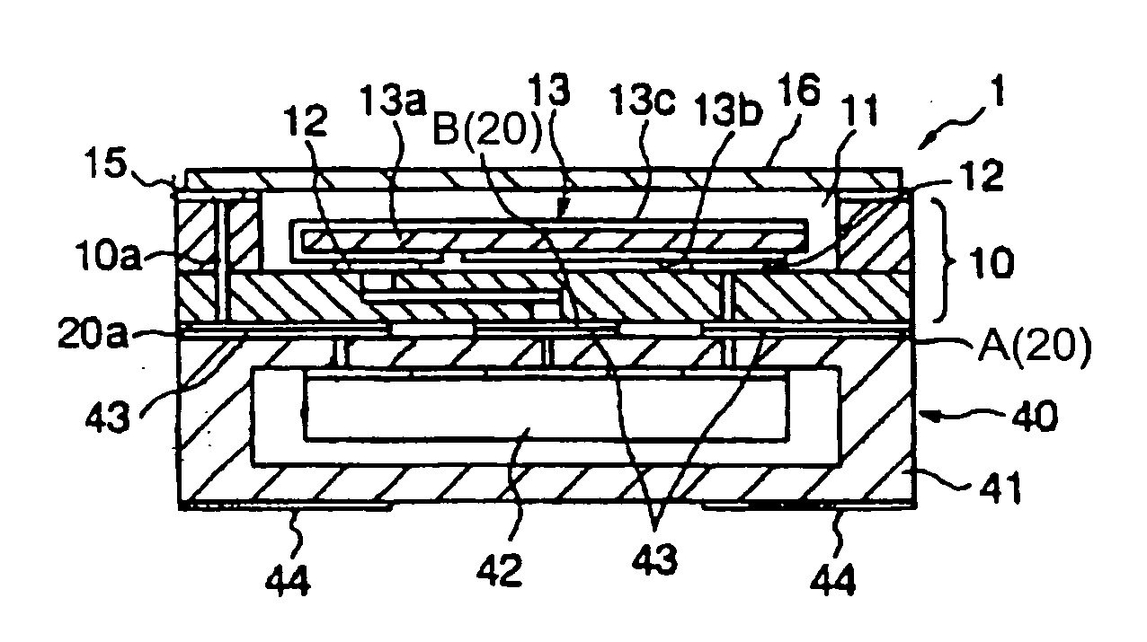
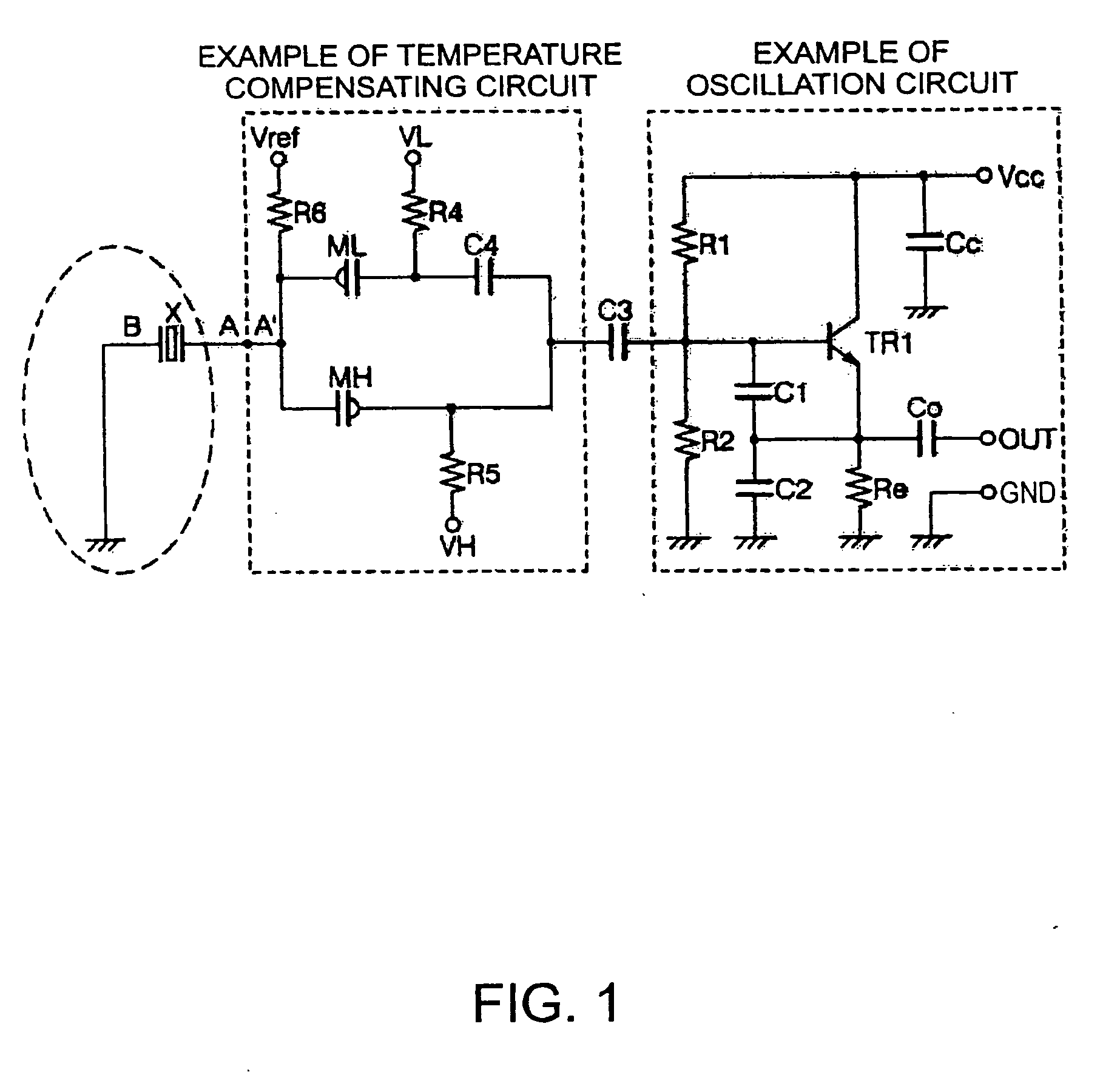
[0030]FIG. 1 is a circuit diagram of a crystal oscillator according to an embodiment of the invention. FIG. 4 shows a sectional view of the crystal oscillator which is assembled with a part including a circuit of the crystal oscillator.

[0031]In the crystal oscillator shown in FIG. 1, for example, an input terminal of a Colpitts oscillator circuit is coupled to an end of a temperature compensating circuit through a capacitor. Other end of the temperature compensating circuit is coupled to a terminal A of a crystal resonator. The other terminal B of the crystal resonator is grounded as designated GND in the figure.

[0032]The Colpitts oscillator circuit and the temperature compensating circuit shown in FIG. 1 are integrated as an IC chip. When settings of the circuits are needed to be changed, a control signal is externally supplied to the IC chip and data in a memory (not shown in the figur...


PUM

PropertyMeasurementUnit
sizeaaaaaaaaaa
capacitanceaaaaaaaaaa
electric characteristicsaaaaaaaaaa

Abstract

A piezoelectric resonator for an oscillator contained in an upper concave portion of an insulating case that has a metal lid with which the upper concave portion is air-tightly closed comprises a GND electrode being conductively coupled to an earth pattern of the piezoelectric resonator and provided on an outer bottom face of the insulating case, a piezoelectric connecting electrode being conductively coupled to an excite electrode of the piezoelectric resonator and provided on the outer bottom face of the insulating case, and an adjustment electrode being conductively coupled to the metal lid and provided on the outer bottom face of the insulating case in such a way that a regulator circuit in an IC part conductively contacts with the adjustment electrode if the IC part including the oscillation circuit is attached to the outer bottom face of the insulating case, wherein the metal lid serves as an adjustment terminal.

Description

[0001]This is a Division of application Ser. No. 11 / 984,082 filed Nov. 13, 2007, which is a Division of Ser. No. 11 / 471,711 filed Jun. 21, 2006 now U.S. Pat. No. 7,468,574. The entire disclosures of the prior applications are hereby incorporated by reference herein in its entirety.BACKGROUND OF THE INVENTION[0002]1. Technical Field[0003]The present invention relates to a piezoelectric resonator for an oscillator and a surface mount type piezoelectric oscillator with which an inconvenience of adjustment work by using a small adjustment terminal provided on a side of a package is eliminated.[0004]2. Related Art[0005]In a mobile communication market, many manufactures of mobile terminal devices promote modularization of parts and components by their functions in consideration of assembly designs, maintenance and handleability of the electric components and compatibility of the components among devices. At the same time, there are strong requests for downsizing of the devices and low ma...

Claims


Application Information

Patent Timeline
Patent Type & Authority Applications(United States)
IPC IPC(8): H01L41/22H05K3/30H10N30/01H10N30/88
CPCH03B5/04H03B5/366Y10T29/42H03H9/0547Y10T29/49128H03H9/0514
Inventor HORIE, KYOKOMAI, MAKOTO
Owner TOYO TSUSHINKI
Learn More