Joining of Concentric Section Polymer Composite Components

Inactive Publication Date: 2009-11-12
COOPERATIVE RESEARCH CENTRE FOR ADVANCED COMPOSITE STRUCTURES
View PDF3 Cites 24 Cited by
  • Summary
  • Abstract
  • Description
  • Claims
  • Application Information

AI Technical Summary

Benefits of technology

[0008]Broadly, the present invention is a method for joining a thermosetting polymer composite component or a thermoplastic polymer composite component to a second component, where the mating surfaces of the components each have at least some points of contact, sufficient to hold the components in their joined state for some time without additional restraint or tooling. The components can be joined together more securely through the application of heat to the joint area, with no external forces required to hold the mating surfaces together during this process. Where the assembled components have mating surfaces consisting of compatible thermoplastic polymers, they can be welded together to make a joint with high joint strength.

Problems solved by technology

Simple joining methods similar to those developed for metallic materials are often unavailable for polymer composites.
Thermosetting composites have poor local plasticity at the surface, and tend to fracture at the surface when similarly pressed together, reducing properties of the thermosetting composite component and likely making the joint ineffectual.
Additionally, to create a strong joint, an adhesive also has to be introduced into the joint area, a difficult task.
However, any subsequent welding operation is likely to melt at least small portions of the thermoplastic composite, causing a loss in dimensional stability.
This can result in distortion of the structure, introduction of voids and other problems likely to reduce the performance of the thermoplastic composite component.
The lack of quick, simple-to-apply joining methods has resulted in the extensive use of mechanical fastening, or the use of liquid and film adhesives, to join composite tubes and similar structures.
Mechanical fasteners are not ideally suited to composites materials, which as a class of materials inherently have low bearing strength.
Additionally mechanical fasteners, while they can be quick to install, reduce the local strength of the composite by introducing a hole.
However, adhesive application can be messy, particularly for insertion of close-fitting components.
Additionally, a good adhesive joint of composite components requires surface preparation of the composite, which can be an extensive and unreliable operation.
Adhesive bonding is thus slow and expensive, requires extensive tooling, and surface preparation is critical.

Method used


Image

  • Joining of Concentric Section Polymer Composite Components
  • Joining of Concentric Section Polymer Composite Components
  • Joining of Concentric Section Polymer Composite Components

Examples


first embodiment

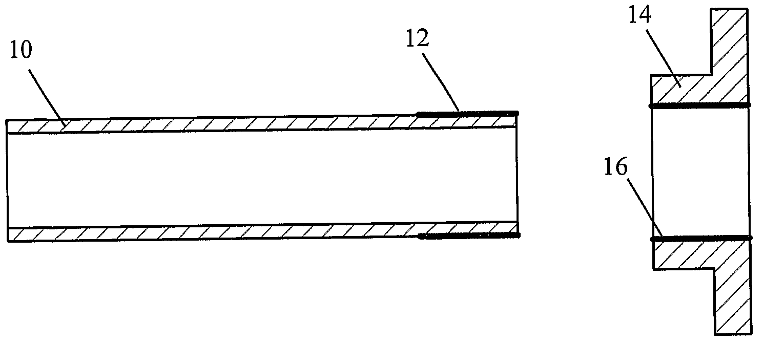
[0060]In the invention, one composite component with a thermoplastic surface is selected for fitting together with a second component, to provide a neat or interference fit between the components in the desired joint area. The second component may be constructed from any material. In the case where reshaping of the second component is desired, a surface that can be easily machined or reshaped is desirable. Fitting of metal components, polymer components and polymer composites to the first composite component is preferable using this technique. Where polymers or polymer composites are utilised, a compliant surface is desirable.

[0061]One principal reason for the use of or attachment of a thermoplastic surface to the first composite component is the ability of the surface thermoplastic material to undergo at least local compressive strain and deform plastically under fitting operations without rupture. A brittle surface material such as that often found in a thermosetting polymer or a ...

second embodiment

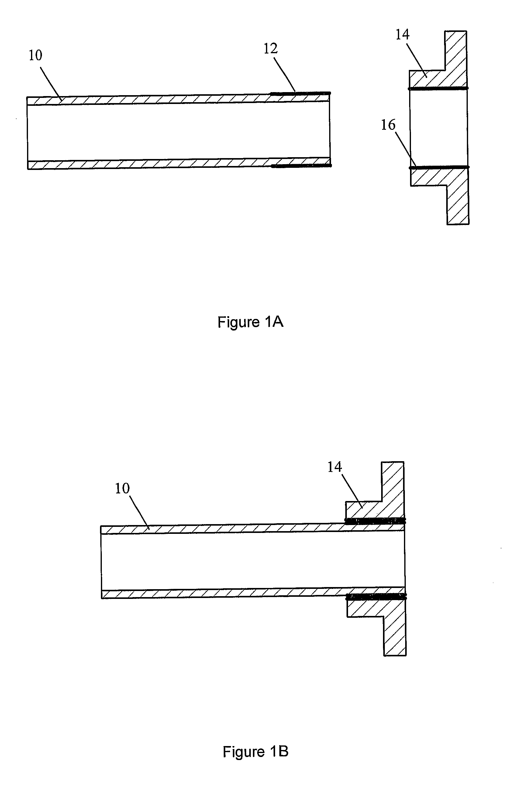
[0065]The surface of the first (12) and / or second (16) component, or at least that part of the component which is to be joined, may be shaped in the next operation. Guidelines for the relative dimensions of parts to be joined by a neat or interference fit may be used for the design of composite components with thermoplastic surfaces, to enable joints of varying tightness and / or required insertion force to be made. Use of the first or second embodiment of the invention, where the components are fixed relative to each other following assembly, relies on the correct choice of relative dimensions between the mating surfaces of the relevant components.

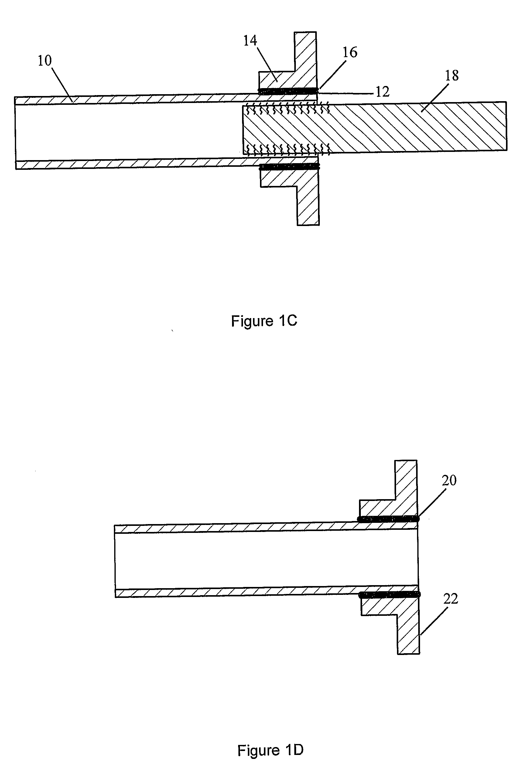
[0066]Locally reprofiling the thermoplastic surface of the composite can be achieved using any of the methods described in PCT / AU2004 / 001272. Tight control of relative dimensions in the joint area will be required to obtain a secure fit, without requiring excessive assembly forces.

[0067]FIG. 1B shows the assembled components. The fitting op...


PUM

PropertyMeasurementUnit
Temperatureaaaaaaaaaa
Pressureaaaaaaaaaa
Electrical conductivityaaaaaaaaaa

Abstract

A process for assembling a composite component with a thermoplastic surface into or around a second component, the process including selecting a first component with a thermoplastic surface and a second component that, when assembled with the first component has at least some points of contact, shaping where necessary at least one component in the joint area, and pressing the components together to achieve relative immobility between the components. A second process involves the selection of a third thermoplastic component to be assembled with the first two components with at least some points of contact with the first and second components are achieved, shaping where necessary, and assembling such that relative immobility is achieved between all three components. In both processes, the joint area is then heated to allow the thermoplastic to flow and preferably weld the assembled components together.

Description

FIELD OF THE INVENTION[0001]The present invention relates to the joining of a polymer composite component with another component. In particular, the invention relates to a polymer composite component with a mouldable thermoplastic surface which allows it to be inserted into or around a second component, leading to a tightly fitted joint. The components should have concentric sections, for at least the proportion of the components to be joined. Optionally the components may be welded together during or subsequent to the insertion operation.BACKGROUND OF THE INVENTION[0002]Composite materials are a class of material which consist of at least two constituent materials, intimately joined together, which together behave as one material, usually with superior properties to either of constituent materials. Fibre reinforced polymer components, otherwise known as polymer composite components, consist of reinforcing fibres held together with a polymer resin, often known as the matrix. The pol...

Claims


Application Information

Patent Timeline
IPC IPC(8): B32B37/06
CPCB29C65/004B29C66/5344B29C65/14B29C65/18B29C65/30B29C65/4815B29C65/5057B29C65/565B29C65/76B29C65/8207B29C66/1122B29C66/21B29C66/242B29C66/24244B29C66/30325B29C66/3452B29C66/612B29C66/721B29C66/73115B29C66/742B29C66/826B29K2023/12B29K2027/16B29K2031/00B29K2063/00B29K2067/00B29K2071/00B29K2101/10B29K2101/12B29K2307/00B29K2995/0039B29K2995/004F16L47/02B29C65/02B29C66/8181B29C66/7394B29C66/7392B29C65/305B29C65/5085B29C65/5071B29C65/3612B29C65/00B29C65/34B29C66/7212B29C66/71B29C66/72525B29C66/73753B29C66/73921B29C66/73772B29C66/73774B29K2995/0008B29C66/73117B29C66/73161B29K2307/04B29K2067/003
Inventor MARELLI, MICHAEL ANDREWBEEHAG, ANDREWPATON, ROWAN
Owner COOPERATIVE RESEARCH CENTRE FOR ADVANCED COMPOSITE STRUCTURES
Why Eureka
Try Eureka