Hybrid vehicle and travel control method of hybrid vehicle

a technology of hybrid vehicles and travel control methods, which is applied in the direction of external condition input parameters, engine-driven generator propulsion, electric devices, etc., can solve problems such as electric power loss, and achieve the effect of preventing erroneous execution and improving fuel consumption in hybrid vehicles

Inactive Publication Date: 2009-11-12
TOYOTA JIDOSHA KK +1
View PDF9 Cites 87 Cited by
  • Summary
  • Abstract
  • Description
  • Claims
  • Application Information

AI Technical Summary

Benefits of technology

[0035]When the vehicle is traveling from the predetermined point, the above structure can prevent erroneous execution of the SOC management that achieves the SOC at the predetermined level in the power storage device when the vehicle arrives at the predetermined point.
[0036]According to the invention, it is possible to improve the fuel consumption in the hybrid vehicle performing the SOC management that achieves the SOC at the predetermined level in the power storage device when the vehicle arrives at the predetermined point.

Problems solved by technology

However, the secondary battery that is typically used as the power storage device generally has such charge / discharge efficiency characteristics that an electric power loss due to an internal resistance and the like changes according to the SOC of the secondary battery.
However, this document has not disclosed the fact that the consideration must be given to the characteristics of the charge / discharge efficiency with respect to the SOC of the battery.

Method used


Image

  • Hybrid vehicle and travel control method of hybrid vehicle
  • Hybrid vehicle and travel control method of hybrid vehicle
  • Hybrid vehicle and travel control method of hybrid vehicle

Examples


first embodiment

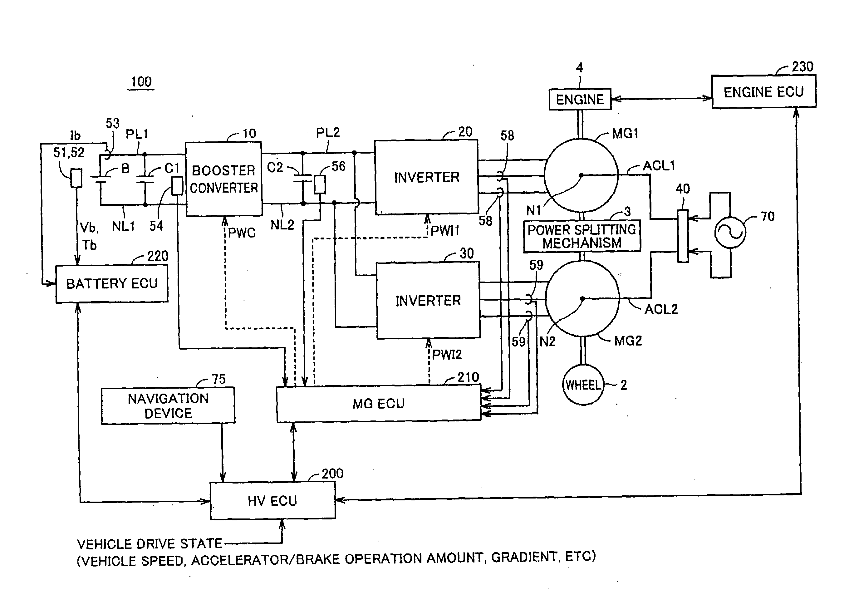
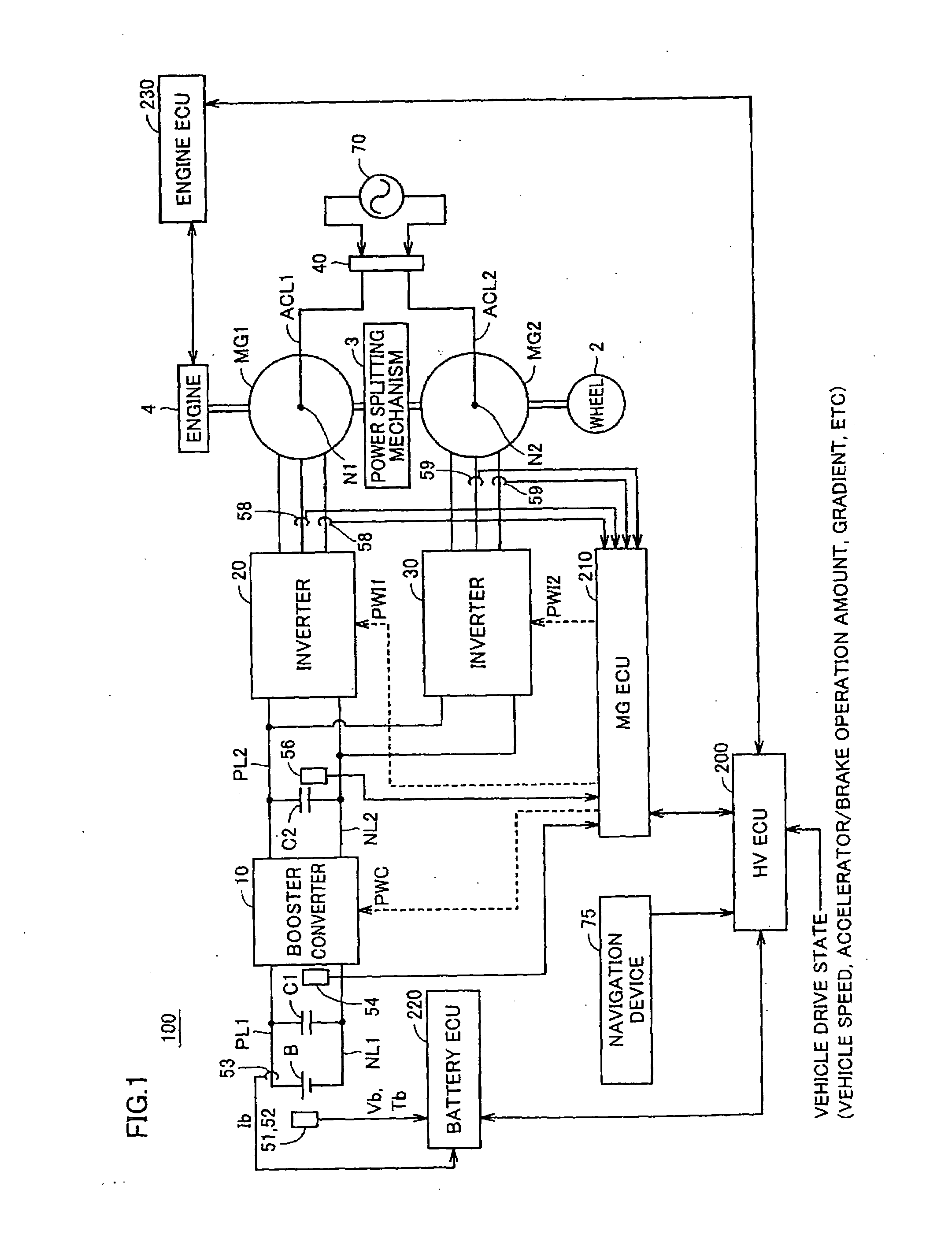
[0053]FIG. 1 is a block diagram illustrating a whole schematic structure of a hybrid vehicle according to an embodiment of the invention.

[0054]Referring to FIG. 1, a hybrid vehicle 100 includes wheels 2, a power splitting mechanism 3, an engine 4 and motor generators MG1 and MG2. Hybrid vehicle 100 further includes a power storage device B, a booster converter 10, inverters 20 and 30, a connector 40, a navigation device 75, capacitors C1 and C2, positive lines PL1 and PL2, and negative lines NL1 and NL2.

[0055]Further, hybrid vehicle 100 includes, as Electronic Control Units (ECUs) for onboard devices, an HVECU 200 controlling a whole hybrid system, an MGECU 210 controlling motor generators MG1 and MG2 as well as booster converter 10 and inverters 20 and 30, a battery ECU 220 controlling a charge / discharge state of power storage device B, and an engine ECU 230 controlling an operation state of engine 4. These ECUs are connected together for mutually transmitting data and information....

second embodiment

[0115]The following embodiments will be described in connection with variations of the travel control of the hybrid vehicle described in connection with the first embodiment. In the following embodiments, therefore, the structure of hybrid vehicle 100 and the SOC management of the power storage device before the arrival at the predetermined point (driver's house) are the same as those of the first embodiment.

[0116]FIG. 9 is a schematic block diagram illustrating the travel control of the hybrid vehicle according to the second embodiment.

[0117]Referring to FIG. 9, output share determining unit 500 in the second embodiment includes an allowed EV travel distance estimating unit 502 and a full charge sensing unit 504.

[0118]Allowed EV travel distance estimating unit 502 estimates, based on the present battery SOC, a distance (allowed EV travel distance) that can be traveled only by the output of motor generator MG2. The allowed EV travel distance can be estimated by successively referrin...

third embodiment

[0131]The third embodiment will be described in connection with the travel control reflecting a progression of deterioration of battery B (power storage device).

[0132]FIG. 12 is a schematic block diagram illustrating the travel control of the hybrid vehicle according to the third embodiment of the invention.

[0133]As can be understood from a comparison between FIGS. 12 and 3, the travel control of the hybrid vehicle according to the third embodiment is further provided with a deterioration determining unit 600. Deterioration determining unit 600 obtains a deterioration degree of battery B (power storage device) based on temperature Tb, current Ib, voltage Vb and the like of battery B.

[0134]For example, the vehicle may enter a diagnosis mode in which battery B outputs a constant pulse-like current after the drive of hybrid vehicle ended, and the deterioration degree of battery B is estimated based on a battery behavior (e.g., a battery voltage behavior or the like after the output of ...


PUM


Abstract

An SOC target is a control target of a remaining capacity of an accumulation device having a characteristic that the internal loss increases in a low SOC region. The SOC target is set to a first value corresponding to a remaining capacity target upon reaching a predetermined point when the remaining travel distance up to a predetermined point where the accumulation device can be charged from outside has become shorter than a predetermined distance. Thus, the hybrid vehicle can perform EV travel by power consumption of the accumulation device. On the other hand, when the remaining travel distance is not smaller than the predetermined distance Dr, the SOC target is set to a second value in the SOC region where the loss of the accumulation device is smaller than the first value. Thus, it is possible to reduce the power consumption in the hybrid vehicle which performs such a remaining capacity management that the remaining capacity of the accumulation device upon arrival at a predetermined point is a predetermined value.

Description

TECHNICAL FIELD[0001]The invention relates to a hybrid vehicle and a travel control method of a hybrid vehicle, and particularly to a hybrid vehicle having, as its power sources, an internal combustion engine and an electric motor that can generate vehicle drive powers, respectively.BACKGROUND ART[0002]In recent years, hybrid vehicles are receiving attention as environmentally friendly vehicles. The hybrid vehicle can generate a vehicle drive power by an electric motor in addition to a conventional engine. Depending on a driving state, the hybrid vehicle can appropriately select a travel manner from among driving only by the engine, driving only by the electric motor and driving by a combination of the electric motor and the engine for improving fuel consumption. Typically, when the vehicle is performing, e.g., low speed travel such as starting and thus is in a drive region of low engine efficiency, the travel control is performed to select an EV mode for driving only by the output ...

Claims


Application Information

Patent Timeline
Patent Type & Authority Applications(United States)
IPC IPC(8): B60W20/00B60K6/48G06F19/00B60W10/26B60W10/08B60K6/445B60L50/16B60W10/06G01C21/26
CPCB60K6/445Y02T10/6239B60L11/123B60L11/14B60L11/1812B60L11/1814B60L11/1861B60L11/187B60L15/007B60L2220/14B60L2220/54B60L2240/62B60L2260/52B60L2260/54B60L2260/56B60W10/06B60W10/08B60W10/26B60W20/00B60W2510/244B60W2510/246B60W2540/04B60W2550/402G01C21/26Y02T10/6217Y02T10/6269Y02T10/6286Y02T10/641Y02T10/7005Y02T10/7022Y02T10/7044Y02T10/705Y02T10/7077Y02T10/7291Y02T10/84Y02T90/127Y02T90/14Y02T90/16Y02T90/161Y02T90/162B60W2710/244B60L11/005Y02T10/7072B60L53/22B60L50/40B60L50/61B60L50/16B60L53/24B60L58/12B60L58/24B60W2540/215B60W2556/50Y02T10/62Y02T10/64Y02T10/70Y02T10/72B60W50/082B60W50/085B60W20/12Y02T90/12
Inventor SOMA, TAKAYAANG, WANLENGNIWA, TOSIAKI
Owner TOYOTA JIDOSHA KK
Why Eureka
Try Eureka