Tidal flow hydroelectric turbine

a hydroelectric turbine and turbine blade technology, applied in the direction of liquid fuel engines, electric generator control, final product manufacturing, etc., can solve the problems of unidirectional force applied to blades and rotors, and achieve the effects of reducing contact and friction, minimizing rotational friction, and increasing thickness

Inactive Publication Date: 2009-11-12
OPENHYDRO GRP LTD
View PDF101 Cites 44 Cited by
  • Summary
  • Abstract
  • Description
  • Claims
  • Application Information

AI Technical Summary

Benefits of technology

[0009]In order to account for water flow in opposing directions, it is necessary to provide bearing or anti-friction means to reduce contact and friction between the outer rim and the annular retaining flanges of the housing in both the inflow and outflow directions. In the preferred embodiment, journals and preferably water lubricated marine bearing plates are utilized to minimize rotational friction between the edges of the outer rim and the retaining flanges of the housing. In the most preferred embodiment, the bearing plates and / or the journals restricting movement in the axial directions are of increased thickness, such that the device remains operational over an extended period of time as these bearings / journals wear away, the rotor being able to shift in the axial direction in response to the direction of water flow.

Problems solved by technology

Because the fluid flow in these turbines is unidirectional, the force applied against the blades and rotors is also unidirectional.

Method used


Image

  • Tidal flow hydroelectric turbine
  • Tidal flow hydroelectric turbine
  • Tidal flow hydroelectric turbine

Examples


Embodiment Construction

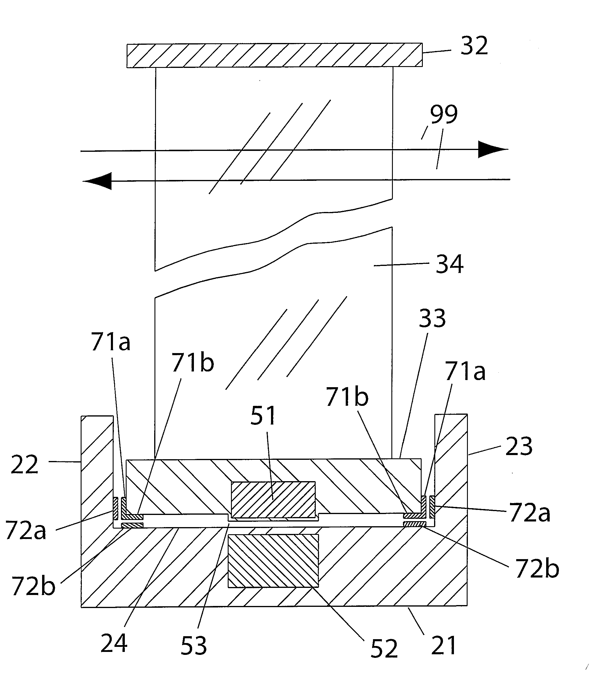
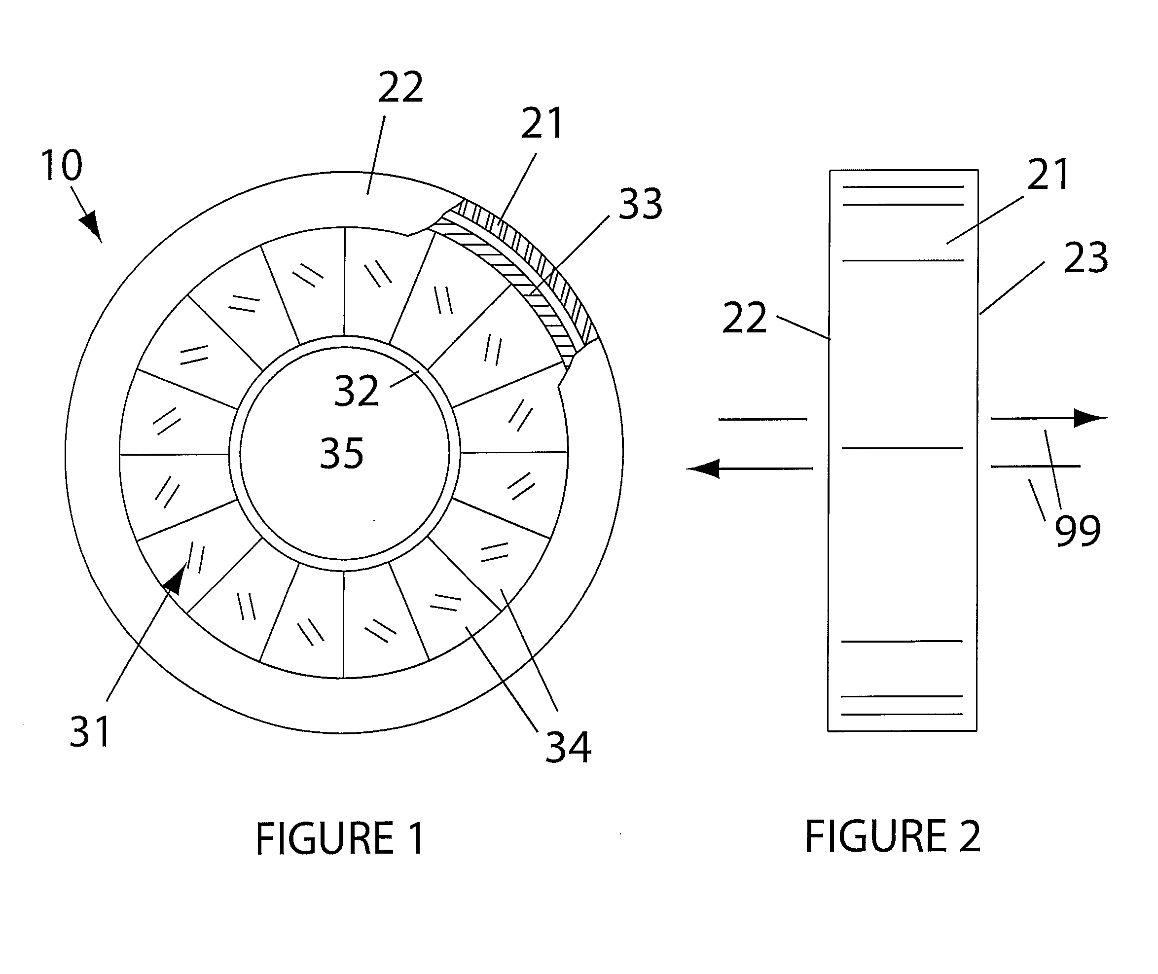
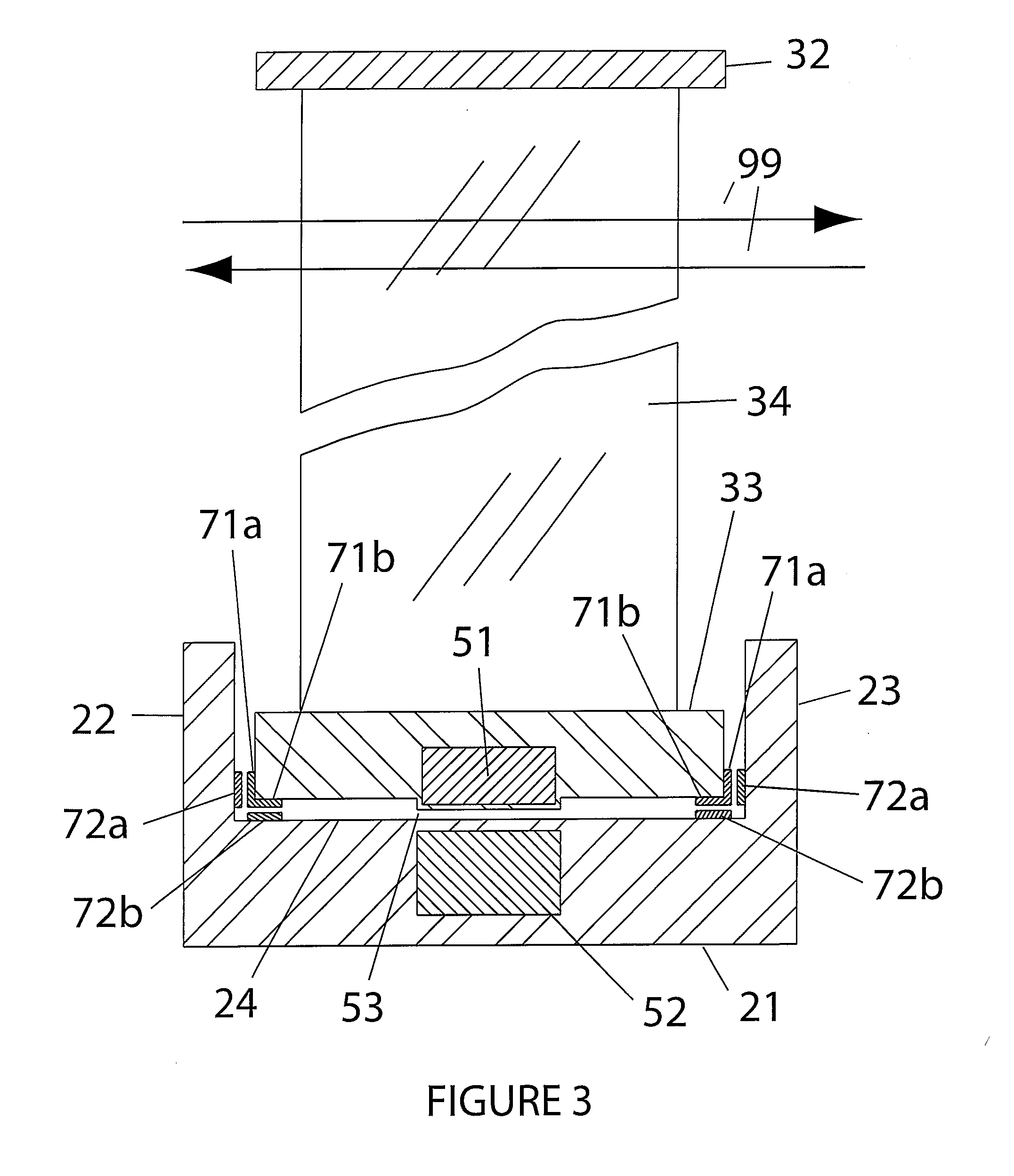
[0017]With reference to the drawings, the invention will now be described in detail with regard for the best mode and the preferred embodiment. In a most general sense, the invention is a device for producing electricity, referred to generally as a hydroelectric turbine or power plant, from low head bi-directional or reversing water flow, particularly and primarily bidirectional water flow resulting from tidal flow, i.e., the cycling movement of water between high tide and low tide conditions.

[0018]As shown generally in FIGS. 1 and 2, a preferred embodiment of the invention is an open-centered hydroelectric turbine 10 comprising a generally annular housing 21. The configuration of housing 21 shown is not meant to be limiting, as other configurations are possible provided the housing 21 accomplishes among other purposes retaining the rotating assembly or rotor 31 concentrically therein while permitting limited axial displacement of the rotor 31, in addition to allowing rotation of th...


PUM


Abstract

A hydroelectric turbine for the production of electricity from tidal flow forces, the turbine having a rotor with an open center such that the blades are mounted between an inner rim and outer rim, wherein retaining members and anti-friction members are provided to limit movement of the rotor relative to the housing in either axial direction, such that water flow in either direction operates the turbine, but wherein the retaining members and the anti-friction members allow the rotor to shift in either axial direction in response to water flow. The anti-friction members limiting rotor travel in the axial direction are preferably of increased thickness, such that as the anti-friction members wear down, the rotor is able to shift relative to the housing in the axial direction.

Description

BACKGROUND OF THE INVENTION[0001]This invention relates generally to the field of turbines or power plants that produce electricity from fluid flow, either air or water, and more particularly relates to such devices wherein the fluid flow causes rotation of a propeller-type or impeller-type rotor, with the rotation being transferred to generators to produce the electricity. Even more particularly, the invention relates to such devices wherein the rotor is an open center rotor capable of rotation in either direction in response to the water flow direction encountered in rising and falling tides.[0002]Production of electricity using hydroelectric or wind-powered turbines is well known. The fluid flow causes rotation of a propeller-type rotor or blades. For wind-powered turbines, the devices are located in areas with steady air currents, and the devices are typically rotated so as to be oriented in the optimum direction for capturing the wind energy. For hydroelectric turbines, the dev...

Claims


Application Information

Patent Timeline
Patent Type & Authority Applications(United States)
IPC IPC(8): F03B13/10F03B13/26F03B11/02
CPCF03B13/10F03B13/264F05B2220/7066Y02E10/28F05B2240/53F16C17/14F16C32/0423F05B2220/7068F16C19/507F16C32/0431Y02P70/50Y02E10/30F03B13/26Y02E10/20
Inventor WILLIAMS, HERBERT
Owner OPENHYDRO GRP LTD
Why Eureka
Try Eureka