Light guide plate structure

Inactive Publication Date: 2009-11-12
WINTEK CORP
View PDF10 Cites 27 Cited by
  • Summary
  • Abstract
  • Description
  • Claims
  • Application Information

AI Technical Summary

Benefits of technology

[0011]The backlight module and the light guide plate thereof according to the embodiments of the invention utilize the combination of the protruding and the indenting curved surfaces of the composite structures to increase the overall surface

Problems solved by technology

However, During the injection molding process, it is common that the surface structure Gc of the light guide plate is poorly formed due to air enclosure between the inden

Method used


Image

  • Light guide plate structure
  • Light guide plate structure
  • Light guide plate structure

Examples


Embodiment Construction

[0021]The following descriptions together with the relevant drawings illustrate the embodiments of the invention in detail so that those who are skilled in the art can implement the invention. It should be noted that, although there are differences in the embodiments of the invention, the structures or the features related to any embodiments of the invention as described in the disclosure can be applied in other embodiments of the invention without deviating from the scope of the invention and should not be construed as any limitation on the implementation of the invention. Besides, it should be recognized that the arrangement and the position of each individual part in the embodiments of the invention, that are explicitly described, can be altered as long as the arrangement and the position are within the scope of the invention. That is, the scope of the present invention is defined by the accompanying claims.

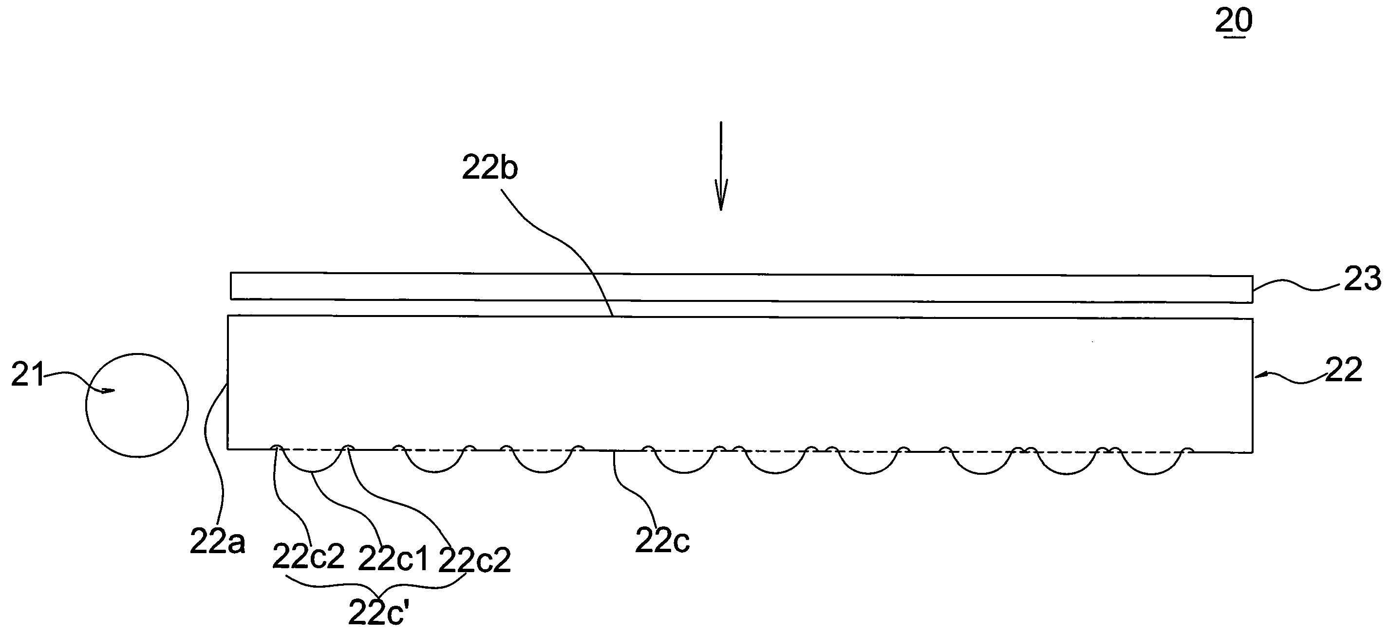
[0022]FIG. 2 shows a schematic diagram illustrating the backlight module ...


PUM


Abstract

The invention discloses a light guide plate structure. The light guide plate structure includes a light-receiving surface, a light-emitting surface and a light-reflecting surface. The light-receiving surface receives emitting light from at least a light source, and the light propagating in the light guide plate exits through the light-emitting surface. The light-reflecting surface is opposite to the light-emitting surface for guiding the light that passes through the light-receiving surface to the light-emitting surface. The light-emitting surface and/or the light-reflecting surface include at least a composite structure. The composite structure includes a primary structure and a secondary structure where the secondary structure is disposed to a side of the primary structure.

Description

BACKGROUND OF THE INVENTION [0001](a) Field of the Invention[0002]The present invention relates to a light guide plate structure, and more particularly, to a light guide plate structure having excellent light guiding efficiency.[0003](b) Description of the Related Art[0004]Currently, most of the light guide plates are processed by etching method and the shape of its surface structure can have a variety of geometrical shapes, such as: circle, rectangle, diamond shape, or the like.[0005]Generally, when producing a light guide plate G as shown in FIG. 1A, an indent structure Tc is usually etched into the stamper T. Then, the light guide plate G is formed on the stamper T by the injection molding method.[0006]However, During the injection molding process, it is common that the surface structure Gc of the light guide plate is poorly formed due to air enclosure between the indenting structure Tc and the injected material. Thus, the geometrical shapes having larger indenting depth (such as...

Claims


Application Information

Patent Timeline
IPC IPC(8): F21V7/22F21S8/10
CPCG02B6/0036
Inventor CHEN, PING-YENGHUANG, KUO-JUIHUNG, TZU TING
Owner WINTEK CORP
Why Eureka
Try Eureka