
Cycloconverter generator

a technology of cycloconverter generator and power circuit, which is applied in the direction of power conversion system, control system, ac-ac conversion, etc., can solve the problems of complicated circuit configuration of cycloconverter generator, and achieve the effect of reducing the number of thyristor power circuits and driving circuits, and simplifying circuit configuration

Active Publication Date: 2009-11-12
HONDA MOTOR CO LTD
View PDF2 Cites 12 Cited by
  • Summary
  • Abstract
  • Description
  • Claims
  • Application Information

AI Technical Summary

Benefits of technology

The invention provides a cycloconverter generator with a simplified circuit configuration that reduces the number of thyristor power circuits and drive circuits. The generator includes a magneto, a bridge circuit with thyristors, and a bridge drive circuit that generates single-phase AC power to be supplied to a load by turning on the thyristors at variable timing. A single DC power supply unit is connected to the single-phase output winding and rectifies the AC power outputted by the winding to DC power. A number of power circuits are connected to the DC power supply unit and supply the rectified DC power as operating power to the thyristors. A number of thyristor drive circuits are connected to the power circuits and drive the thyristors. The thyristor drive circuits are individually used to drive in common ones among the thyristors such that the number of drive circuits is made smaller than the number of thyristors. This simplifies the circuit configuration and reduces the number of components needed for the generator.

Problems solved by technology

This type of cycloconverter generator has a complicated circuit configuration because each of the twelve thyristors is generally driven independently by a separately provided power circuit and drive circuit.

Method used


Image

  • Cycloconverter generator
  • Cycloconverter generator
  • Cycloconverter generator

Examples


Embodiment Construction

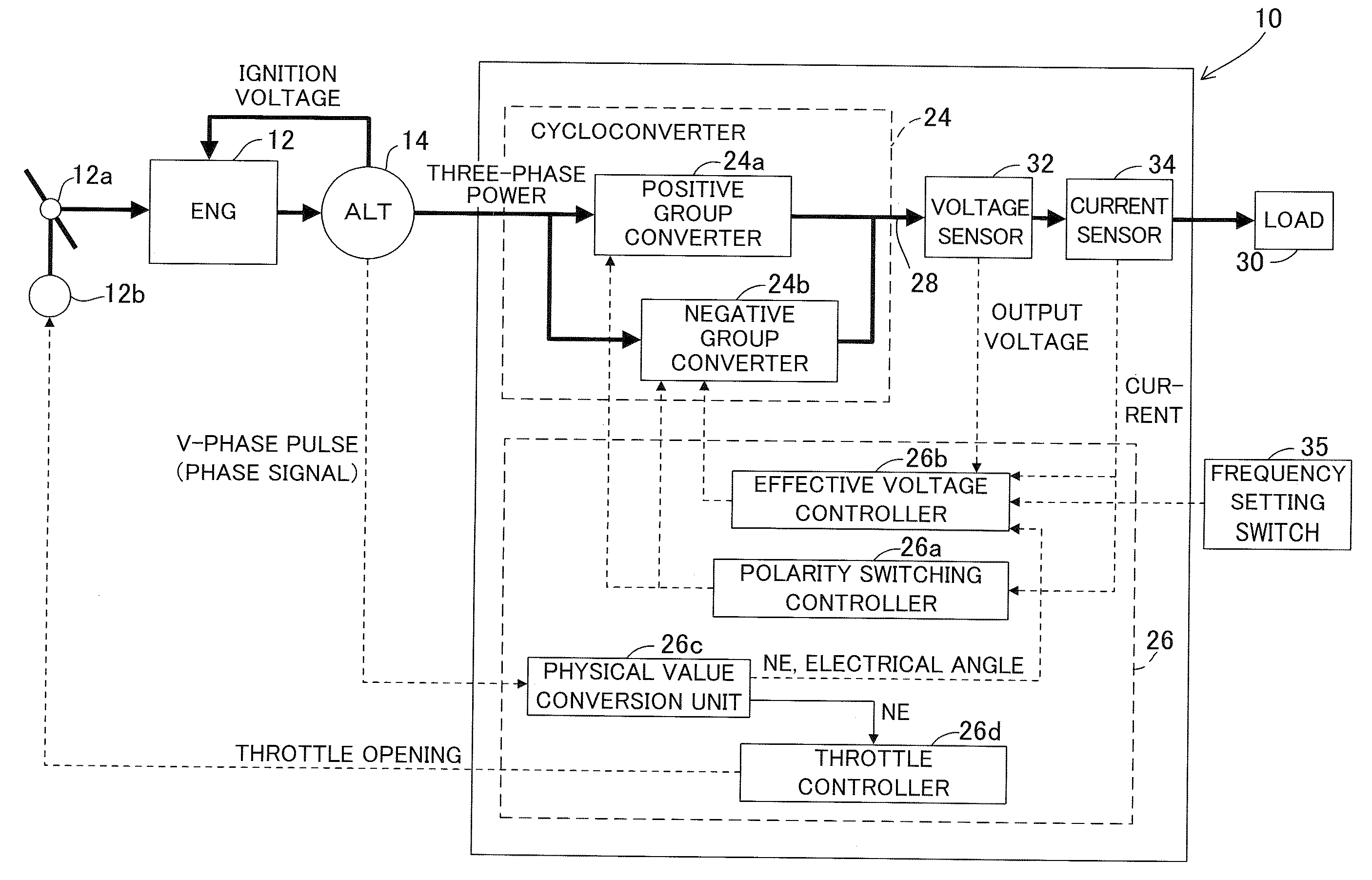
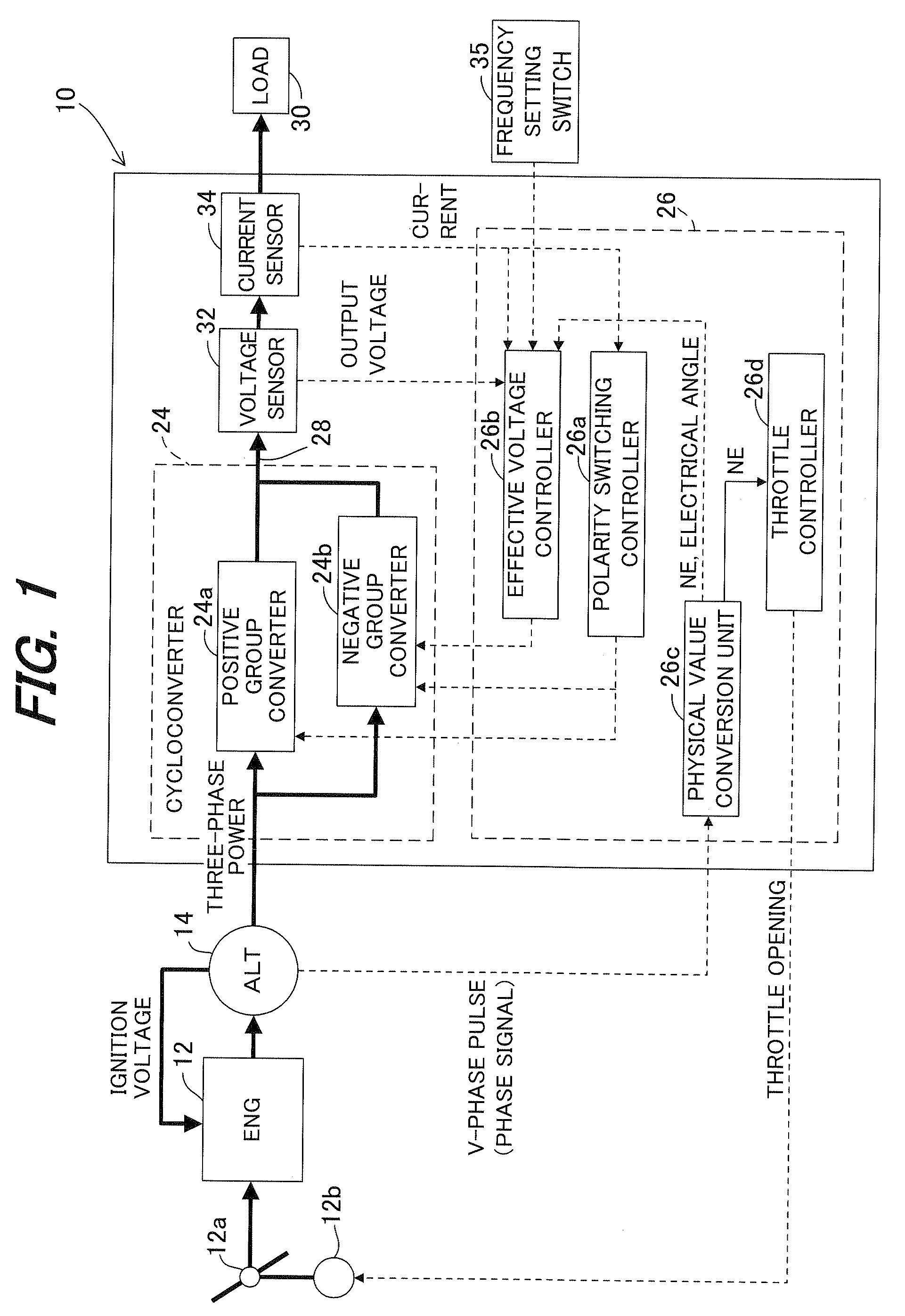
[0024]FIG. 1 is a block diagram showing the overall configuration of the cycloconverter generator according to the present invention.

[0025]Reference numeral 10 is assigned to the cycloconverter generator in FIG. 1. The generator 10 is equipped with an internal combustion engine 12 (named ENG in the drawing). It has rated outputs of AC 100 V-2.3 kVA and DC 12 V-10 A. The engine 12 is an air-cooled, spark ignition unit whose throttle valve 12a is moved by an actuator 12b comprising a stepper motor or the like. It is started using a recoil starter (not shown).

[0026]The generator 10 is equipped with a magneto 14 (named ALT in FIG. 1) that is driven by the engine 12.

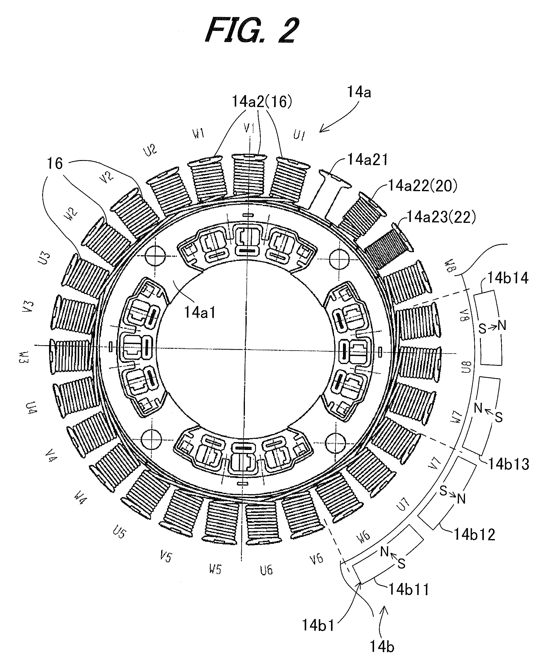
[0027]FIG. 2 is a plan view of a stator 14a of the magneto 14.

[0028]The stator 14a is equipped with a stator core 14a1 fastened near the cylinder head of the engine 12. As illustrated, twenty-seven teeth 14a2 are formed to project radially from the stator core 14a1. Twenty-four of the teeth 14a2 are wound with coils Un, Vn an...


PUM


Abstract

In a cycloconverter generator, there are provided, q number of power circuits that supply rectified DC power of a DC power supply unit as operating power to the p (p>q) number of thyristors, and r (p>r) number of thyristor drive circuits that are connected to the q number of the power circuits and drive the p number of the thyristors, wherein the r number of the thyristors drive circuits are individually used to drive in common ones among the p number of the thyristors whose operation is unaffected even if driven at the same timing such that the number r of the drive circuits is made smaller than the number p of the thyristors, thereby enabling to simplify circuit configuration.

Description

BACKGROUND OF THE INVENTION[0001]1. Field of the Invention[0002]This invention relates to a cycloconverter generator, namely a generator that converts AC power of a given frequency to another frequency for output.[0003]2. Description of the Related Art[0004]The cycloconverter generator that produces an output by converting AC power of a given frequency to another frequency is well known. A description of the cycloconverter generator technology can be found, for example, in Japanese Patent No. 3447934. The cycloconverter generator described in this reference is equipped with twelve thyristors bridge-connected in antiparallel connection to three-phase output windings in the positive and negative directions and generates single-phase alternating current of a desired frequency by turning on the thyristors at variable timing (width or angle) every half-period of the desired alternating current frequency.SUMMARY OF THE INVENTION[0005]This type of cycloconverter generator has a complicated...

Claims


Application Information

Patent Timeline
Patent Type & Authority Applications(United States)
IPC IPC(8): H02M5/257
CPCH02M5/271H02P27/16H02M5/273
Inventor INAGAWA, TOSHINORINAKAYAMA, SHINSAKUMASUBUCHI, YOSHINORI
Owner HONDA MOTOR CO LTD
Learn More