Automatic packet tagging

a packet tagging and packet technology, applied in the field of network devices, can solve the problems of inability to detect qos parameters directly from packet contents, or perform bandwidth measurement for that purpose, and achieve the effect of convenient detection

Inactive Publication Date: 2009-11-12
KONINKLIJKE PHILIPS ELECTRONICS NV
View PDF24 Cites 65 Cited by
  • Summary
  • Abstract
  • Description
  • Claims
  • Application Information

AI Technical Summary

Benefits of technology

[0011]In an embodiment of the network device the determining means are arranged for detecting the source of the received data packet based on at least one of a network address indicator; a network port indicator; a media access indicator; and, in the event of the first network segment being part of the Internet, an Internet Protocol [IP] address; a Uniform Resource Locator [URL]. This has the advantage that the source can be easily detected during the setup of a link via the device, and/or from control data associated to the data packets, like packet headers.
[0012]In an embodiment of the network device the determining means are arranged for said assigning the type of service by applying predefined criteria, the criteria including at least one of a mapping of a content type to a source, and priority criteria for a s

Problems solved by technology

However, a problem of the known method occurs when a large number of packets arrive from a further network segment, for example from the internet.

Method used


Image

  • Automatic packet tagging
  • Automatic packet tagging
  • Automatic packet tagging

Examples


Embodiment Construction

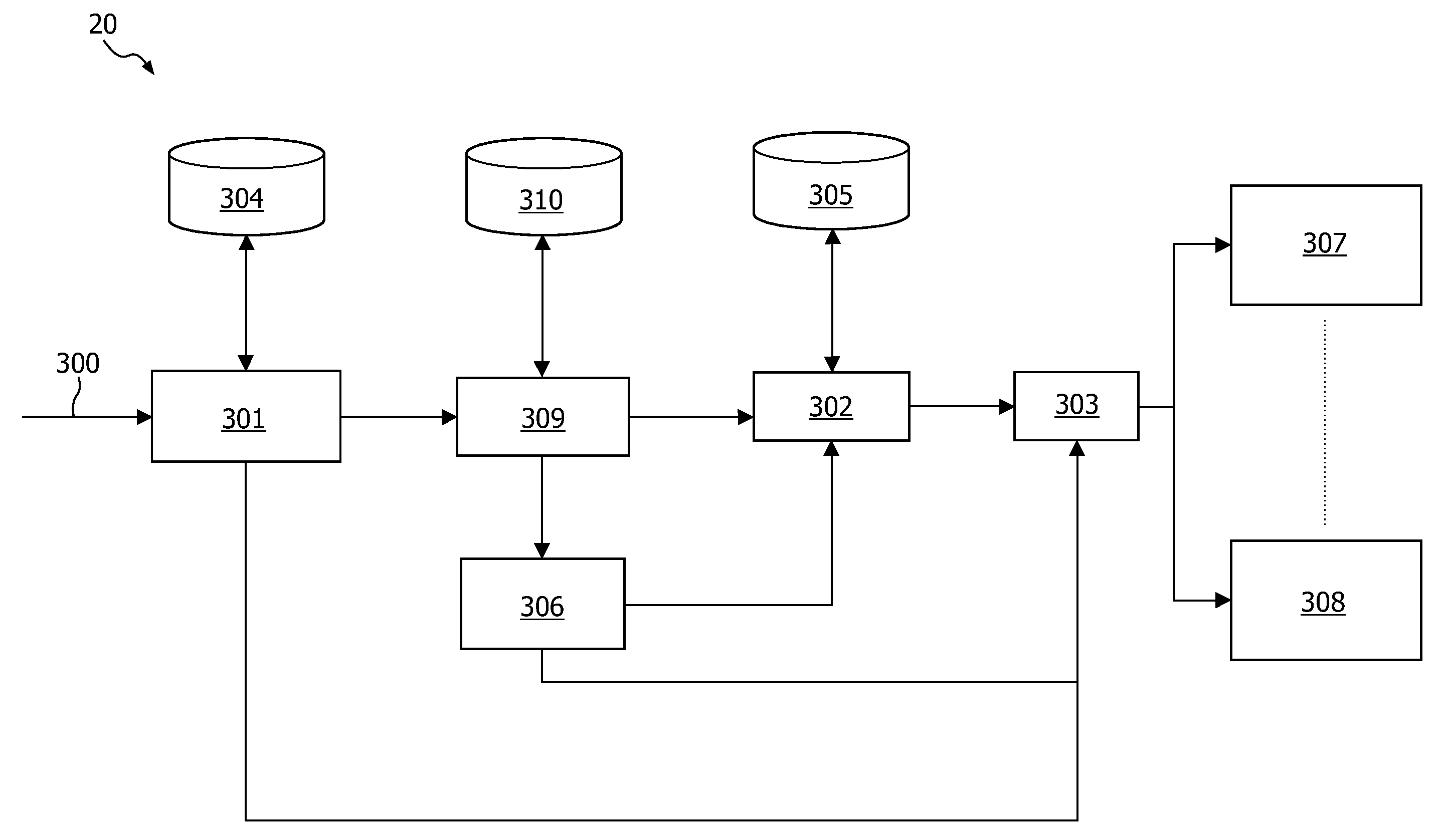
[0025]FIG. 1 shows a network device in a network. The network has a first network segment 18, for example a wide area network [WAN] like the Internet, which is coupled to at least one source 30, and a second network segment 17, for example a local area network [LAN], coupled to at least one target, whereas the network device 20 is coupled to both network segments. Data packets may be exchanged between the source and target via the network. The source, for example a server providing a website to the internet, has a network interface 31, and one or more applications or services 32 that are able to communicate to the target by exchanging data packets via the network. The target 10, for example a home computer accessing the internet, has at least one application 12 and a control unit 13, and an interface unit 11 coupled to an antenna 14 for accessing a wireless network segment.

[0026]Priority-based Quality of Service (QoS) data communication is starting to be deployed in home networks th...


PUM


Abstract

A network device is arranged for coupling to a first network segment (18) to a second network segment (17), and has a transfer unit (23) for transferring data packets between the first and second network segments. The device has a determining unit (24) for determining a service requirement for a received data packet for accommodating the service requirement in the second network segment. A source of the received data packet in the first network segment is detected. Based on priority criteria and content type criteria a type of service is tagged to the data packet in dependence of the source. The transfer unit is arranged for accommodating the type of service in the second network segment. Advantageously a bridge is formed for transferring data packets that are unaware of quality of service to a network segment that operates according to quality of service requirements.

Description

FIELD OF THE INVENTION[0001]The invention relates to a network device comprising a first interface unit for coupling to a first network segment, a second interface unit for coupling to a second network segment, transfer means for transferring data packets between the first and second network segments, and determining means for determining a service requirement for a received data packet that is to be transferred from the first network to the second network segment, for accommodating the service requirement in the second network segment.[0002]The invention further relates to a method of determining a service requirement while transferring data packets between a first network segment and a second network segment, the method comprising the steps of determining a service requirement for a received data packet that is to be transferred from the first network to the second network segment, for accommodating the service requirement in the second network segment.[0003]The invention relates ...

Claims


Application Information

Patent Timeline
IPC IPC(8): H04L12/56
CPCH04L29/06027H04L65/104H04L67/2828H04L67/2823H04L67/322H04L65/103H04L67/5651H04L67/565H04L67/61H04L65/1101
Inventor MOONEN, JAN RENIER
Owner KONINKLIJKE PHILIPS ELECTRONICS NV
Why Eureka
Try Eureka