
Niobium silicide-based turbine components, and related methods for laser deposition

a technology of niobium silicide and turbine components, which is applied in the field of metal and metal alloys, can solve the problems of complex and expensive processes, reducing the oxidation resistance of alloys, and affecting the performance of turbine components

Inactive Publication Date: 2009-11-12
GENERAL ELECTRIC CO
View PDF24 Cites 27 Cited by
  • Summary
  • Abstract
  • Description
  • Claims
  • Application Information

AI Technical Summary

Benefits of technology

The invention relates to a turbine component made from a niobium silicide-based composition that is compositionally-graded through at least a portion of its structure. The invention also includes a turbine blade made from a niobium silicide alloy and a process for fabricating a niobium silicide-based turbine article with a pre-selected shape and thickness. Additionally, the invention provides a method for repairing a damaged segment of a turbine component formed of a material comprising niobium silicide by replacing or modifying it with at least one replacement material comprising niobium silicide using a laser cladding process.

Problems solved by technology

However, adjustment of the composition to satisfy these requirements is sometimes achieved only at the expense of other properties.
For example, the oxidation resistance of the alloy may decrease, which can be problematic for other portions of the blade, such as the blade tip.
However, these processes can be complicated and expensive.
For example, obtaining the exact, specified blade shape can require many individual steps, which usually conclude with time-consuming machining steps, to provide the final geometric configuration.
Obtaining the proper dovetail geometry is also a complex endeavor, and often requires a large number of time-consuming, post-machining operations.
Formation of these regions also requires complex procedures.
Formulating the proper core composition (especially when new types of alloys are being cast) is yet another challenge in efficiently manufacturing blades and other components by conventional techniques.

Method used


Image

  • Niobium silicide-based turbine components, and related methods for laser deposition
  • Niobium silicide-based turbine components, and related methods for laser deposition
  • Niobium silicide-based turbine components, and related methods for laser deposition

Examples


Embodiment Construction

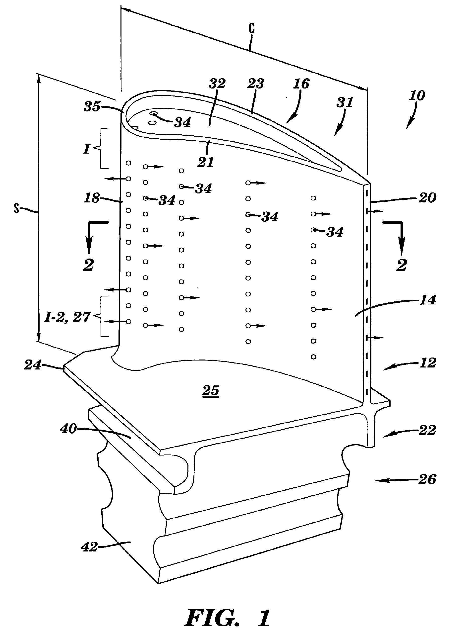
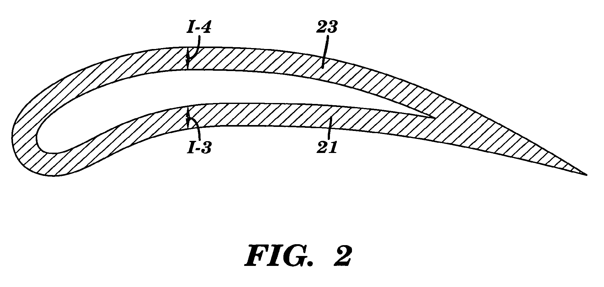
[0029]FIG. 1 is a perspective view of an exemplary gas turbine engine rotor blade 10. Turbine blades of this type are well-known in the art. Non-limiting examples include various blade designs described in U.S. Pat. Nos. 5,458,461 (C. P. Lee et al) and 5,690,472 (C. P. Lee), which are incorporated herein by reference. Usually, a plurality of such blades are attached to an annular rotor disk (not shown). Blade 10 includes an airfoil 12, having pressure and suction sides 14, 16, and leading and trailing edges 18, 20, respectively. The sidewalls 21 and 23 of the airfoil define the pressure and suction sides 14 and 16. The sidewalls are generally opposite each other in a plane with a vertical dimension of the airfoil.

[0030]The lower part of the airfoil in FIG. 1 terminates with a base 22. Base 22 includes a platform 24, on which the airfoil can be rigidly mounted in upright position, i.e., substantially vertical to the top surface 25 of the platform. The base further includes a dovetail...


PUM

PropertyMeasurementUnit
temperaturesaaaaaaaaaa
melting temperaturesaaaaaaaaaa
operating temperaturesaaaaaaaaaa

Abstract

A turbine component formed from a niobium silicide-based composition is described. The component can be compositionally-graded through at least a portion of its structure. A turbine blade formed from a composition which includes a niobium silicide alloy is also described. The blade includes an airfoil; an airfoil tip region; a platform on which the airfoil is mounted; and a dovetail root attached to an underside of the platform. The niobium silicide alloy in at least one portion of the turbine blade is compositionally different from the niobium silicide alloy in another portion of the blade. Processes for fabricating a niobium silicide-based turbine article are also described, using laser cladding techniques. Repair methods are also set forth in the application.

Description

[0001]This application is a Divisional Application of application Ser. No. 11 / 172,390, filed Jun. 30, 2005.BACKGROUND OF THE INVENTION[0002]This invention relates generally to metals and metal alloys used in high temperature applications. More specifically, the invention relates to niobium-silicide compositions which are useful for a variety of turbine engine components.[0003]Equipment used in high temperature applications can be made from a variety of high-performance alloys. Choice of a particular alloy depends in large part on the projected temperature-exposure of the component, along with other specified requirements for the component. They include: strength, creep resistance, wear resistance, oxidation resistance, environmental resistance, weight requirements, and the like. Gas turbine engines are a good example of how the many alloy properties need to be balanced throughout a single (albeit complex) piece of equipment. In a typical gas turbine engine, air is compressed in a co...

Claims


Application Information

Patent Timeline
Patent Type & Authority Applications(United States)
IPC IPC(8): C23C6/00B05D3/00B05D3/12
CPCB22F5/009B23K35/327B22F2998/00B23K26/1411B23K26/34B23K2201/001B23P6/007B23P15/02C22C27/02C22C29/18C23C24/10C23C26/02F01D5/005F01D5/28F01D5/288B22F5/04B23K26/328F05D2230/80F05D2230/13F05D2230/31F05D2300/2261F05D2230/90C23C28/042C23C28/044C23C28/048C23C28/321C23C28/341C23C28/3455C23C28/347C23C28/36B23K26/3206B23K26/3213B23K26/322B23K26/3226B22F2207/01B23K26/32B23K26/144B23K2101/001B23K2103/08B23K2103/18B23K2103/26B23K2103/50
Inventor BEWLAY, BERNARD PATRICKAZER, MAGDI N.CRETEGNY, LAURENTRITTER, ANN MELINDAYOUNG, CRAIG DOUGLAS
Owner GENERAL ELECTRIC CO
Learn More