Optical Triggering System For Stroboscopy, And A Stroboscopic System

a stroboscopic system and optical triggering technology, applied in the field of optical triggering system for stroboscopic system, can solve the problems of limited flash frequency of ordinary bulb/light source-stroboscopic system, inability to observe the vibratory movement of human vocal folds during phonation by human eye, inconsistent image hue under two kinds of illumination, etc., to achieve more accurate frequency information, improve the observation of vibratory object, and improve the effect of vibratory information

Inactive Publication Date: 2009-11-12
CYMO
View PDF2 Cites 98 Cited by
  • Summary
  • Abstract
  • Description
  • Claims
  • Application Information

AI Technical Summary

Benefits of technology

[0018]Such a triggering system allows more accurate frequency information to be obtained because the vibratory information is obtained from the light reflected or transmitted from said vibratory object in response to the projected light. Hence, the vibratory information is obtained from the vibratory object in a more direct manner, and is less likely to be influenced by other objects. Accordingly, the vibratory information is more accurate.
[0019]An additional advantage which may be obtained with such a triggering system is that, since the vibratory information is converted into triggering signals for the stroboscope system, the stroboscope system will allow an improved observation of the vibratory object.
[0020]Another additional advantage which may be obtained with such a triggering system, is that the vibratory information can be obtained with less computational effort, for example by determining the interval between maxima in the light received from or transmitted by the vibratory object.
[0021]Another additional advantage which may be obtained with such a triggering system is that it can be implemented in the stroboscopic system and be applied substantially without additional invasive procedures or contact between the stroboscopic system and the vibratory object or the surrounding environment of the vibratory object.

Problems solved by technology

For instance, the vibratory movements of human vocal folds during phonation are too fast to be observed by human eye.
However, a disadvantage of this system is that the maximum flash frequency of an ordinary bulb / light source-stroboscope is limited and typically does not exceed 1 000 flashes per second maximally, with a flash duration of about 10 to 30 microseconds.
Therefore, the two light sources have different radiation spectra which results in inconsistent hue of the images under the two kinds of illumination.
A disadvantage of this energy transferring circuit is that it generates a noise in the frequency range audible by the human auditory system, which not only may be perceived as annoying but may also disturb measurements of e.g. the sounds produced by the human vocal system.
However, a disadvantage of the system known from these ‘Hess’ documents is that a high brightness of the LEDs is required, which causes a high degree of heat dissipation, which can cause burning of the cavity of the human body in which the rigid endoscope is inserted, e.g. the mouth.
The heat dissipation also reduces the life span of the LEDs.
However, this apparently simple system is cumbersome and rarely applied in practice because it has to be triggered by the person being examined and the examiner.
However, this alternative has the same drawbacks because of the mechanical rotating disc.
Furthermore, a mechanical noise will be introduced.
However, a disadvantage is that it is very difficult to measure the fundamental frequency accurately, because in chest voice signal the dominating frequency typically is the second harmonic of the fundamental frequency.
For instance, it is impossible to obtain a fundamental frequency from a non-periodic signal.
However, a disadvantage is that it is difficult to get vibratory information when the sensor is not placed in the correct position or the sensor moves out of the correct position.
However, like the contact vibration sensor, this requires an accurate positioning of the probing electrodes on the skin, near the larynx and might influence the medical examination.
Accordingly, a common disadvantage of the prior art triggering mechanisms described above is that it is difficult to obtain accurate frequency information from the vibratory object.

Method used


Image

  • Optical Triggering System For Stroboscopy, And A Stroboscopic System
  • Optical Triggering System For Stroboscopy, And A Stroboscopic System
  • Optical Triggering System For Stroboscopy, And A Stroboscopic System

Examples


Embodiment Construction

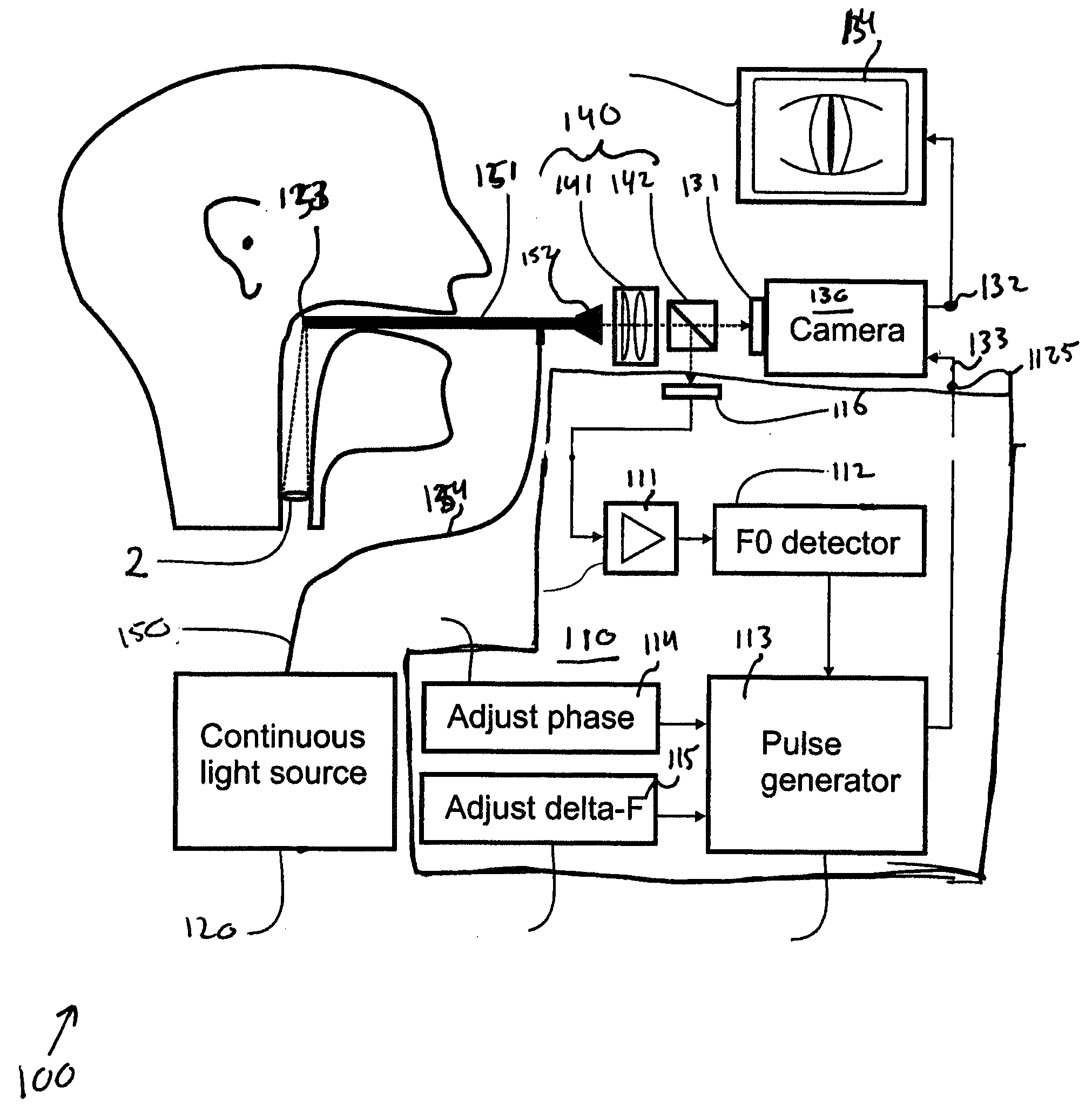
[0037]Referring first to FIG. 1, an example of an embodiment of a triggering system 110 is shown, implemented in a stroboscopic system 100. By way of example, FIG. 1 illustrates the application of the stroboscopic system in medical stroboscopy, more in particular in laryngostroboscopy. In this respect, laryngoscopy refers to an examination of the larynx (voice box). A laryngoscope refers to an instrument that is used to obtain a view of the larynx. Glottography is a general term used for methods to monitor the vibrations of the glottis, i.e. the vocal folds, which is a part of the larynx. However, the invention is not limited to medical stroboscopy, but can also be applied in industrial stroboscopy.

[0038]The shown example of a stroboscopic system 100 includes a triggering system 110, a light source 120 which in an active state projects light onto an object 2 and an image generating system 130 which in an active state generates an image of the object 2 from light reflected from and / o...


PUM


Abstract

A triggering system for a stroboscope system, comprising: a light source for projecting light on a vibratory object, such as vocal folds, an optical sensor for sensing light reflected or transmitted from said vibratory object in response to the projected light, in order to obtain vibratory information from the vibratory object; and a control arrangement connected to the optical sensor, for converting the vibratory information into triggering signals for the stroboscope system, said electronic control arrangement including a control output connectable to said stroboscope system, for outputting said triggering signals to said stroboscope system.

Description

FIELD OF THE INVENTION[0001]The present invention relates to a triggering system for a stroboscope system, and to a method for generating triggering signals. The invention further relates to a stroboscope system, and use thereof and to a method for stroboscopy. The invention further relates to information obtainable by a triggering system or a stroboscope system. The invention also relates to a laryngoscope.BACKGROUND OF THE INVENTION[0002]Historically, a convenient method of getting a slow motion effect from high-speed vibratory movements which are too fast to be observed directly by the human eye, and hence appear only as a blur, is using the stroboscopic phenomenon. Most people are acquainted with this phenomenon. If a regular vibratory object is illuminated by short light flashes of the same frequency as the vibrations, the object will appear immobile. Likewise, if it is illuminated by flashes of a somewhat lower or higher frequency than the vibrations it appears to move slowly ...

Claims


Application Information

Patent Timeline
Patent Type & Authority Applications(United States)
IPC IPC(8): A61B1/267
CPCA61B1/2673A61B5/11A61B5/0059
Inventor QIU, QUINJUNSCHUTTE, HARM KORNELISVAN GEEST, LAMBERTUS KAREL
Owner CYMO
Why Eureka
Try Eureka