Push-button blood control

a push-button and blood control technology, applied in the direction of haemostasis valves, valves, other medical devices, etc., can solve the problems of time-consuming and inefficient catheterization occluding the patient's vein with the clinician's finger or fingers, and inefficient use of constricting bands or pressure cuffs

Active Publication Date: 2009-11-12
BECTON DICKINSON & CO
View PDF80 Cites 60 Cited by
  • Summary
  • Abstract
  • Description
  • Claims
  • Application Information

AI Technical Summary

Benefits of technology

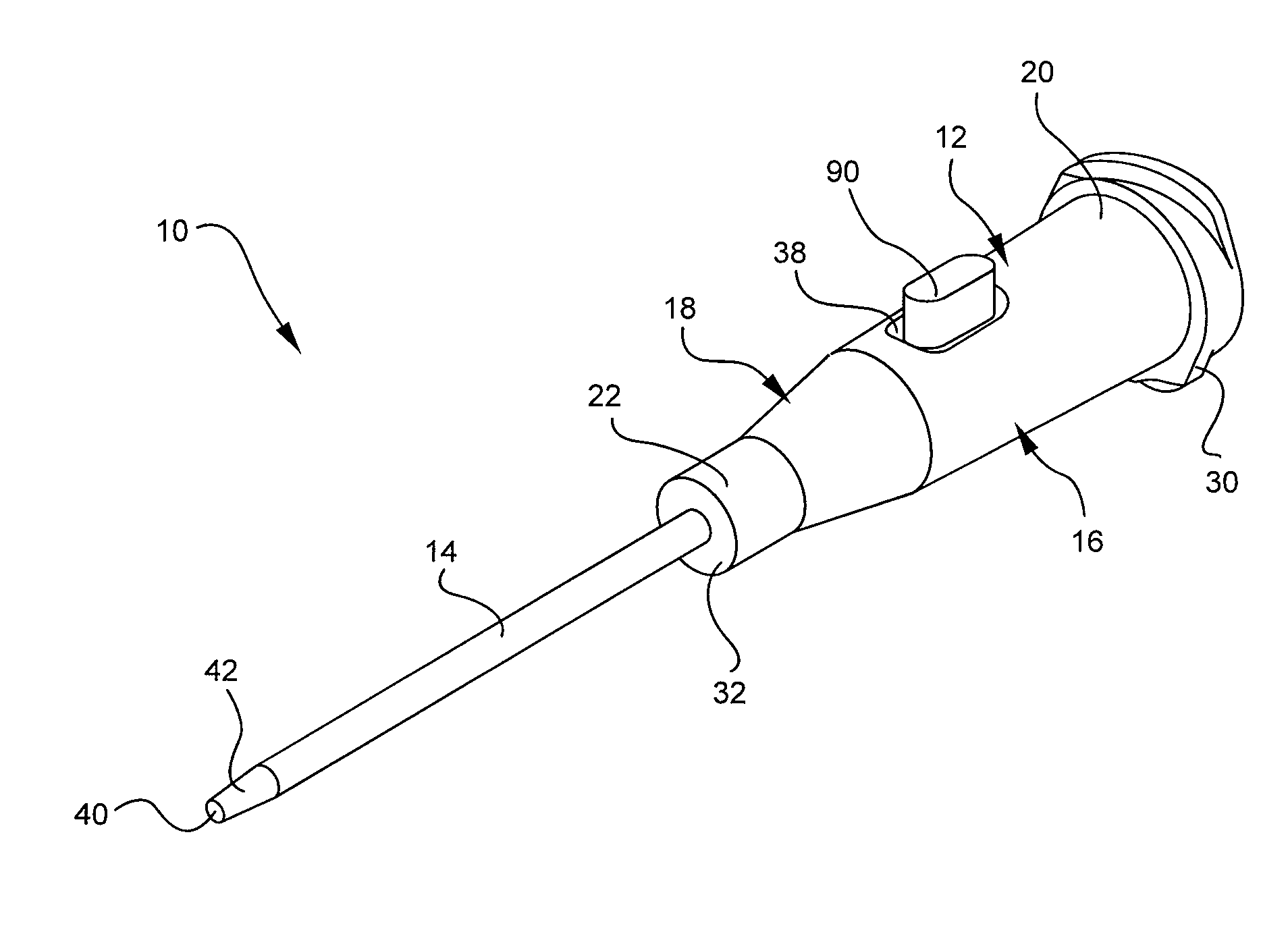
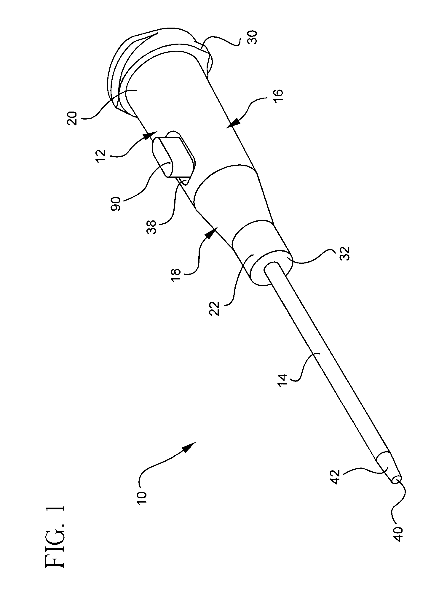
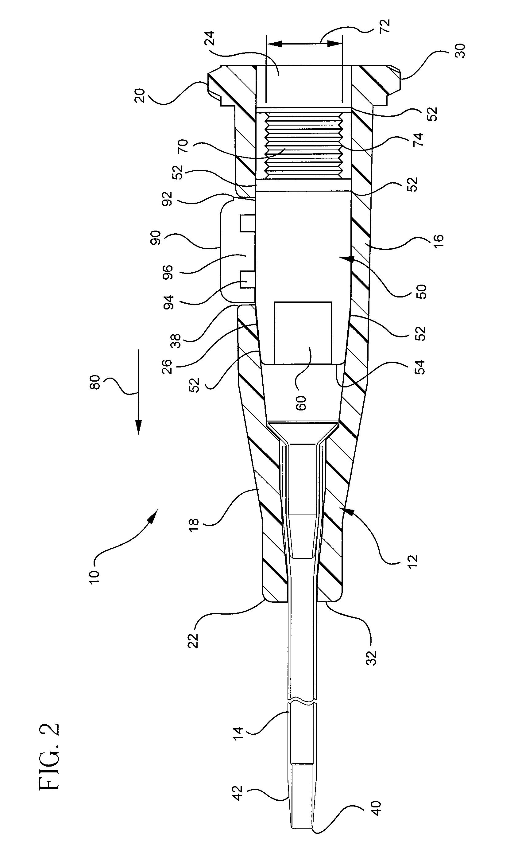
[0014]By default, the septum is in a closed state. Therefore, by default, a fluid is unable to pass or flow through the slit or opening of the septum. As such, a clinician may insert the catheter into a patient, remove an introducer needle from the catheter assembly and the blood of the patient is prevented from flowing through the catheter assembly. Once the catheter is inserted, the clinician may defeat or actuate the septum of the catheter adapter to allow blood to flow through the catheter assembly. The septum may be actuated either by applying pressure to an outer surface of the septum, or by inserting a probe through the inner membrane of the septum.

Problems solved by technology

Use of a constricting band or pressure cuff is undesirable due to the difficulty associated with monitoring flashback through the catheter assembly.
Aside from requiring additional equipment, the use of a constricting band or pressure cuff is time consuming and inefficient for catheterization.
Occluding the patient's vein with the clinician's finger or fingers is similarly constraining and inefficient.
However, the clinician must maintain contact with the patient or the blood will flow uncontrollably from the catheter assembly and create a risk of undesirable exposure.
Therefore, if the clinician chooses to occlude the vein in this manner, the clinician is restricted to only one free hand with which to provide additional medical care to the patient until the catheter is further connected to an infusion system or clamped.
Firstly, the clinician may attach a vacuum tube or collection vial to the end of the catheter adapter and draw blood from the patient.
In some cases, the negative pressure of the vacuum collection vial causes the patient's catheterized vein to collapse.
Additionally, collapsing the vein may damage the vein of the patient as well as cause bruising and tenderness to the patient.
Secondly, the clinician may allow the blood to flow freely from the catheter adapter and collect the patient's blood in a collection vial.
This method of collection is also undesirable due to the clinician's need to use both hands in collecting, labeling and storing the blood samples.

Method used


Image

  • Push-button blood control
  • Push-button blood control
  • Push-button blood control

Examples


second embodiment

[0067]Referring now to FIG. 10, a cross-sectional side view of a catheter assembly 200 is show. In this embodiment, the catheter assembly is modified to include an actuator 210. The actuator 210 is generally tubular with an outer diameter 212 selected to slidably nest within the docking portion 70 of the septum 50. The actuator 210 further includes a flange 214 comprising the proximal end of the actuator 210. The flange 214 comprises an outer diameter that is greater than the inner diameter 72 of the docking portion 70 of the septum 50. As such, the flange 214 is prevented from moving beyond the proximal end 76 of the docking portion 70 of the septum 50. The actuator 210 may be further retained within the catheter adapter body 16 by modifying the catheter adapter body 16 to include an inner compartment 18. The inner compartment 18 comprises actuator stop 218 to prevent the actuator 210 from exiting the catheter adapter 12 through the proximal end 20 opening. The actuator stop 218 co...

third embodiment

[0072]Referring now to FIG. 13, a catheter assembly 300 is shown. The present embodiment comprises a catheter adapter body 312 and a catheter 14. The catheter 14 is comparable to the catheter 14 of the previous embodiment as described in connection with the previous figures. The catheter adapter body 312 comprises a rigid or semi-rigid material for encasing a flexible or semi-flexible septum 350. The catheter adapter body 312 generally comprises an outer shell or exoskeleton-like covering for the septum 350. The material of the catheter adapter body 312 is generally selected such that a set of threads 330 may be provided at the proximal end 320 of the catheter assembly 300. The material of the threads 330 must be sufficiently rigid such that a complementary set of threads may be coupled thereto. For example, a complementary set of threads may be incorporated into a component of an infusion system. As such, the component may be coupled to the catheter assembly 300 by engaging the thr...


PUM


Abstract

A device for controlling fluid flow through an indwelling catheter assembly. The device includes a septum that is closed by default but that may be defeated temporarily by either exerting a force on a contact surface of the septum, or by biasing the septum with a probe.

Description

BACKGROUND OF THE INVENTION[0001]The present disclosure relates generally to infusion therapy practice and procedures. Specifically the present disclosure relates to an indwelling catheter assembly for use in artificial dialysis, fluid infusion, or blood infusion, and more particularly to an indwelling catheter assembly which provides flow control for a fluid passing through the catheter assembly.[0002]Typically, catheter assemblies comprise a catheter adapter and a catheter wherein a lumen of the catheter adapter and a lumen of the catheter are in fluid communication. Upon insertion of the catheter into the vasculature of a patient, the blood of the patient flow freely though the catheter and into the lumen of the catheter adapter. This blood flow is termed “flashback” and is desirable to ensure proper insertion of the catheter. To prevent undesirable exposure to the blood, a clinician will typically control the blood flow through the catheter assembly by occluding the catheterized...

Claims


Application Information

Patent Timeline
Patent Type & Authority Applications(United States)
IPC IPC(8): A61M25/18
CPCA61M39/0613A61M39/0693A61M2039/064A61M39/06A61M2039/062A61M2039/0673A61M2039/0036
Inventor HARDING, WESTON F.MCKINNON, AUSTIN JASON
Owner BECTON DICKINSON & CO
Why Eureka
Try Eureka