Dual roll blind system

a blind system and double-roll technology, applied in the direction of curtain suspension devices, door/window protective devices, shutters/movable grilles, etc., can solve the problems of many inconveniences in use of casings, high complex structure, etc., to achieve low manufacturing and maintenance costs, simple operation of an operation chain, and simplified structure

Inactive Publication Date: 2009-11-19
KIM JUNG MIN
View PDF5 Cites 23 Cited by
  • Summary
  • Abstract
  • Description
  • Claims
  • Application Information

AI Technical Summary

Benefits of technology

[0008]In the present invention, it is possible to adjust a light shading degree based on an overlapping state of a light transmission part and another light transmission part or a light transmission part and a non-light transmission part by horizontally moving one of two blind raw materials in a left direction or a light direction in which a light transmission part and a light non-transmission part having a constant width are alternately formed. A structure...

Problems solved by technology

So, the structure is so complicated, and manufacturing the same costs too much.
It is needed to separately operate the winding apparatus and the feeding apparatus, thus casing many inconvenience when in use.
In addition, since a winding roll is pushed and fed with the help of a difference between a long direction size and a short direction size in a horizontal direction movement with a sliding friction contact in a horizontal directio...

Method used


Image

  • Dual roll blind system
  • Dual roll blind system
  • Dual roll blind system

Examples


Embodiment Construction

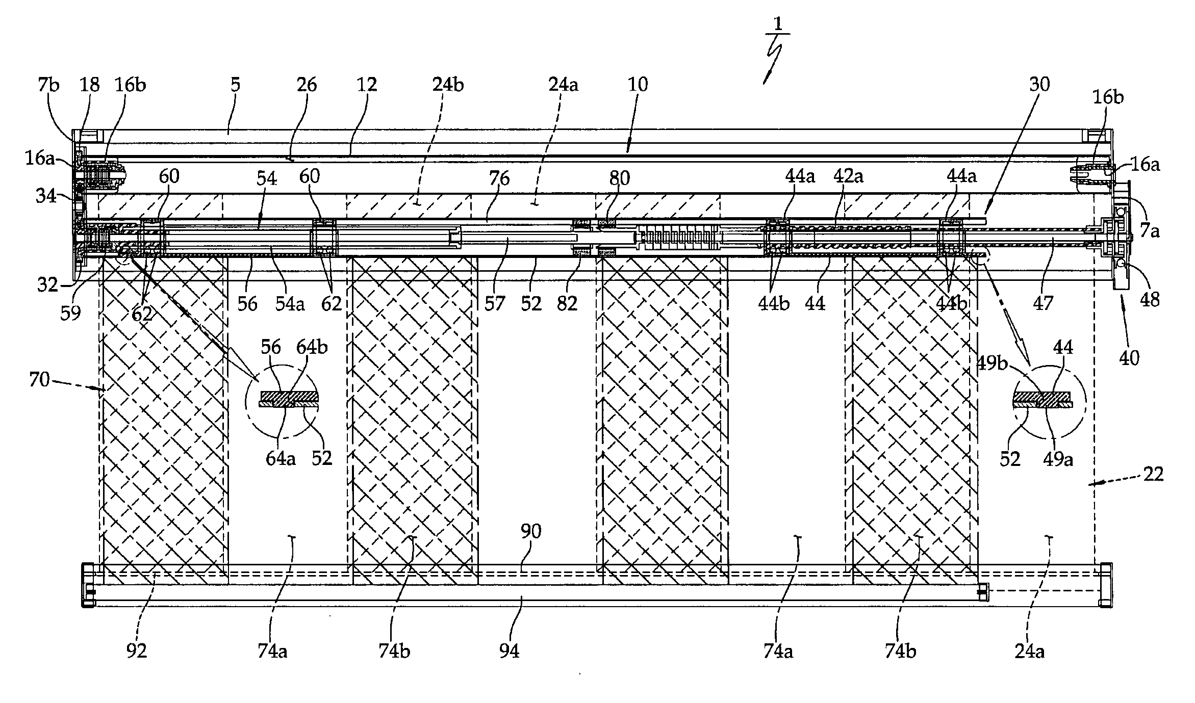
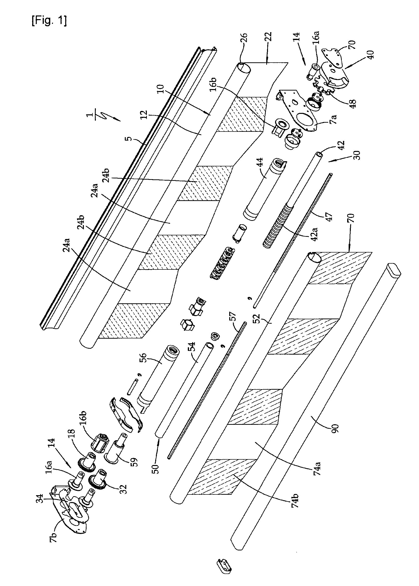
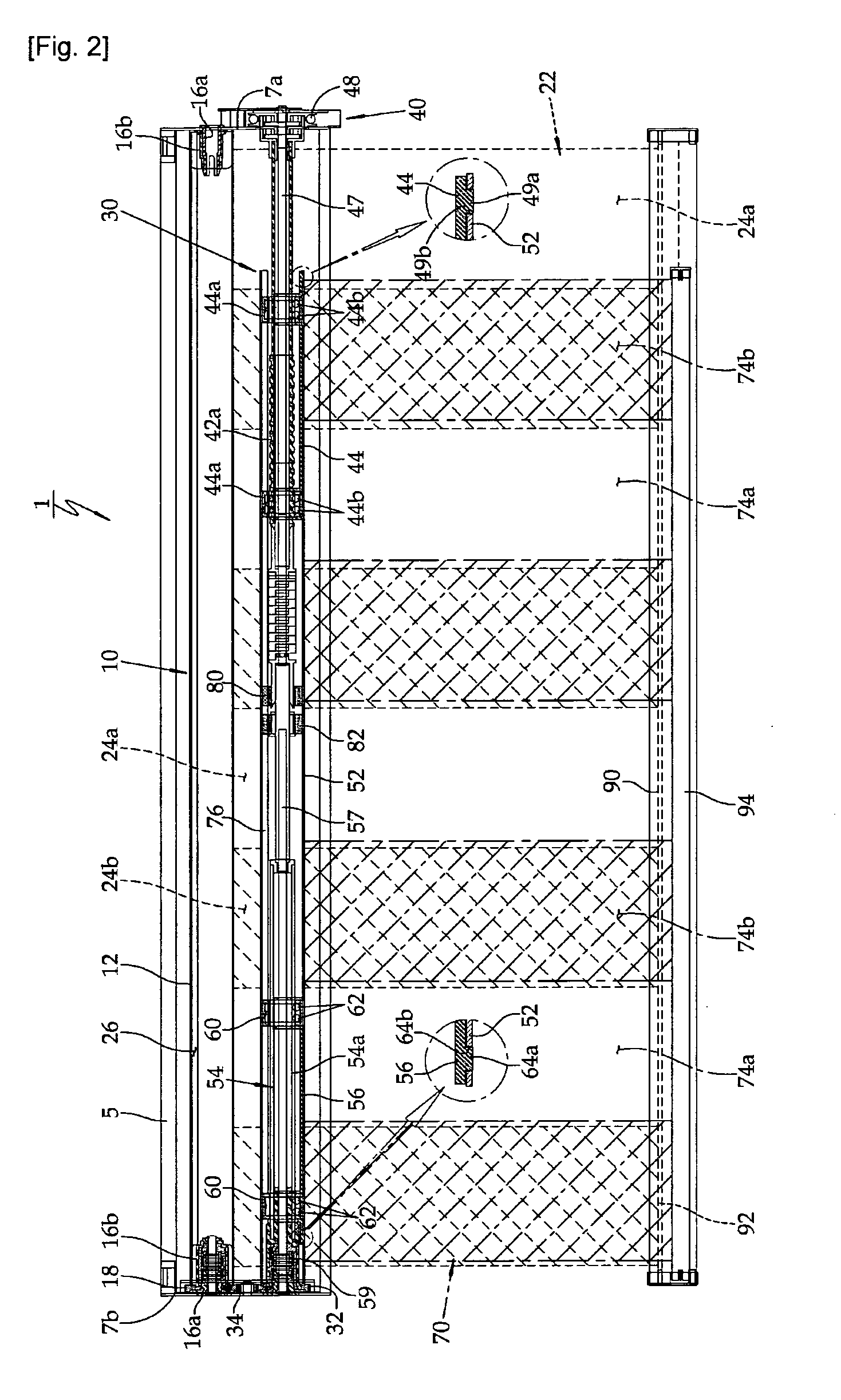
[0021]To achieve the above object, there is provided a dual roll blind system which is able to adjust a light shading degree, a dual roll blind system which comprises a winding roll which includes a roll casing rotatably supported between both side plates of a ceiling bracket; a driving winding roll which includes a moving member disposed between both side plates in parallel with the winding roll and is thread-engaged with a screw shaft rotating by means of a blind winding device of one side, a straight moving member which is provided for left and right straight movements by restricting the rotation of the moving member, and a roll casing engaged with the moving member and the straight moving member; a first blind raw material of which upper end is fixed at the winding roll and in which a light transmission part and a light non-transmission part having constant widths are alternately formed in a width wise direction; a second blind raw material of which upper end is fixed at the dri...


PUM


Abstract

A dual roll blind system is able to adjust a light shading degree and comprises a winding roll which includes a roll casing rotatably supported between both side plates of a ceiling bracket; a driving winding roll which includes a moving member disposed between both side plates in parallel with the winding roll and is thread-engaged with a screw shaft rotating by means of a blind winding device of one side, a straight moving member which is provided for left and right straight movements by restricting the rotation of the moving member, and a roll casing engaged with the moving member and the straight moving member; a first blind raw material of which upper end is fixed at the winding roll and in which a light transmission part and a light non-transmission part having constant widths are alternately formed in a width wise direction; a second blind raw material of which upper end is fixed at the driving winding roll and which has a light transmission part and a light non-transmission part corresponding to the first blind raw material and is movable left and right; and a counter weight bar which fixes a lower end of the first blind raw material with a lower end of the second blind raw material being slidably inserted into the counter weight bar in a parallel direction.

Description

TECHNICAL FIELD[0001]The present invention relates to a dual roll blind system which is able to adjust a light shading degree, and in particular to a dual roll blind system in which it is possible to easily adjust an indoor light shading function as a light transmission part and a light non-transmission part formed on two blind raw materials are overlapped by moving at least one of two blind raw materials in a left or right direction with the help of an operation chain, and it is possible to easily adjust an up and down height.BACKGROUND ART[0002]As disclosed in a Korean utility model registration number 20-0401004, a conventional blind system is designed to perform a light transmission, partial light shading, and full light shading operation by adjusting an overlapping of two sheets of a polarization screen by moving one of two winding rolls using a feeding part having a cam.[0003]The conventional blind system is provided with a winding roll feeding apparatus which is formed of a h...

Claims


Application Information

Patent Timeline
IPC IPC(8): E06B9/40
CPCA47H23/06E06B9/40E06B2009/405E06B2009/2452E06B2009/2405E06B9/78E06B9/42
Inventor KIM, JUNG-MIN
Owner KIM JUNG MIN
Why Eureka
Try Eureka