Lane departure warning and change assist system utilizing active materials

a technology of active materials and assist systems, applied in brake systems, process and machine control, instruments, etc., can solve the problems of adding to ineffective shoulder methods, and increasing the cost of the vehicle, so as to avoid the additional cost of warning generation, reduce energy consumption, and be ready to implement

Inactive Publication Date: 2009-11-19
GM GLOBAL TECH OPERATIONS LLC
View PDF33 Cites 60 Cited by
  • Summary
  • Abstract
  • Description
  • Claims
  • Application Information

AI Technical Summary

Benefits of technology

[0012]It will be understood and appreciated that the present invention provides a number of advantages over the prior art, including, for example, providing a readily implemented system in vehicles having existing MR-HPS systems, and avoiding the additional cost for warning generation. The inventive system provides the benefits of lowering energy consumption to effect a warning, thereby reducing the load upon the charging system, increasing reliability by reducing the number of moving parts, reducing the mass of the vehicle by eliminating electro-mechanical components, and providing modality in preventing improper lane changes, in comparison to conventional electrically driven steering wheel warning (e.g., vibration) systems.

Problems solved by technology

Further, LDW / LCA systems offer effective warning alerts for vehicles in central lanes, wherein shoulder methods would be ineffective.
A common type of haptic alert is to use a haptic seat; this type of system, however, has been found to add to the cost of the vehicle.
In this configuration, EPS (Electric Power Steering) or EHPS (electro-hydraulic power steering) are conventionally used to generate steering vibration; however, these systems also add to the cost, and often require high peak electric current and / or voltage.
In addition, it is appreciated that a steering torque in the opposite direction caused by the electric motor may cause a wrong reaction from the driver.

Method used


Image

  • Lane departure warning and change assist system utilizing active materials
  • Lane departure warning and change assist system utilizing active materials
  • Lane departure warning and change assist system utilizing active materials

Examples


Embodiment Construction

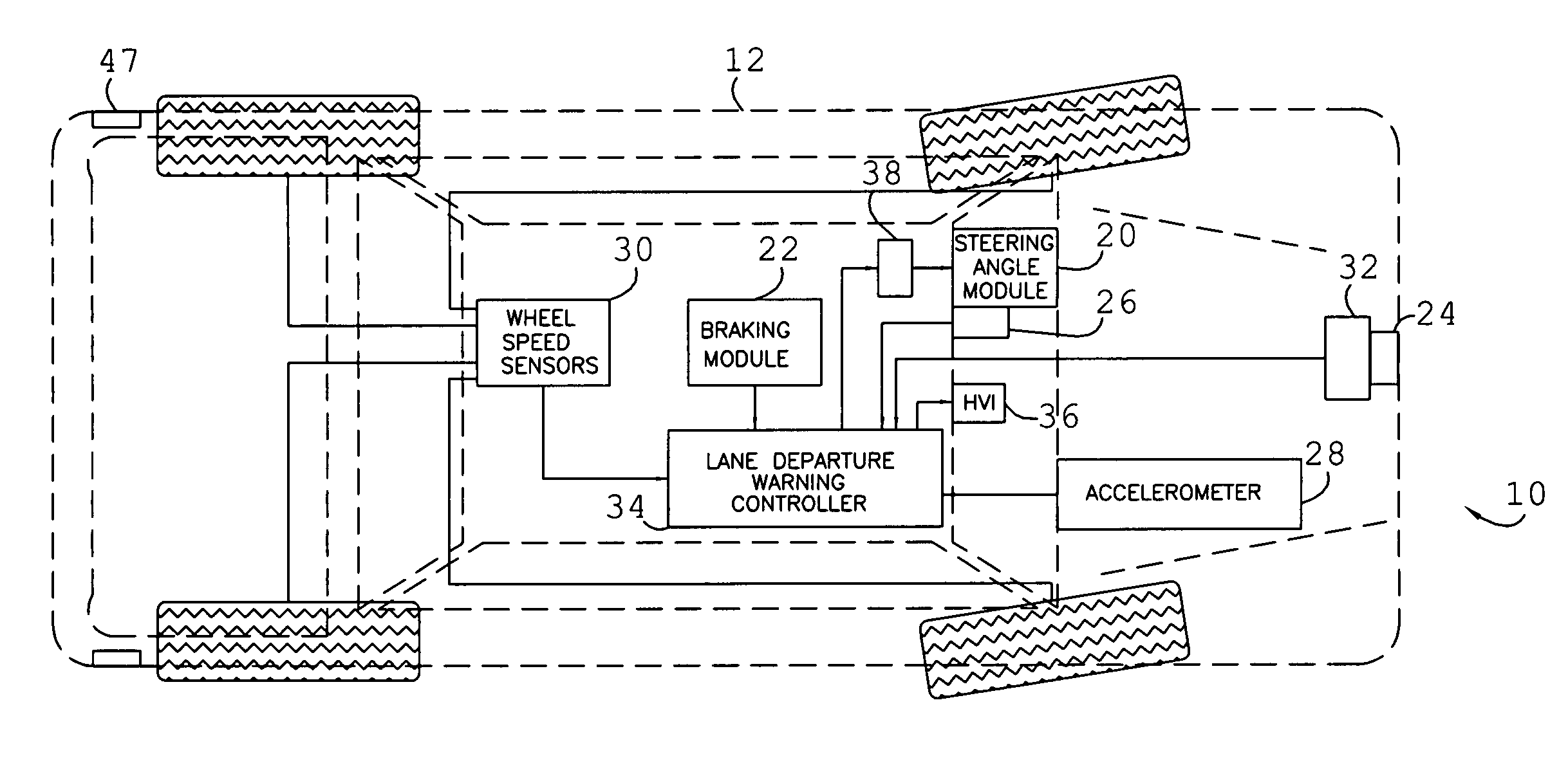
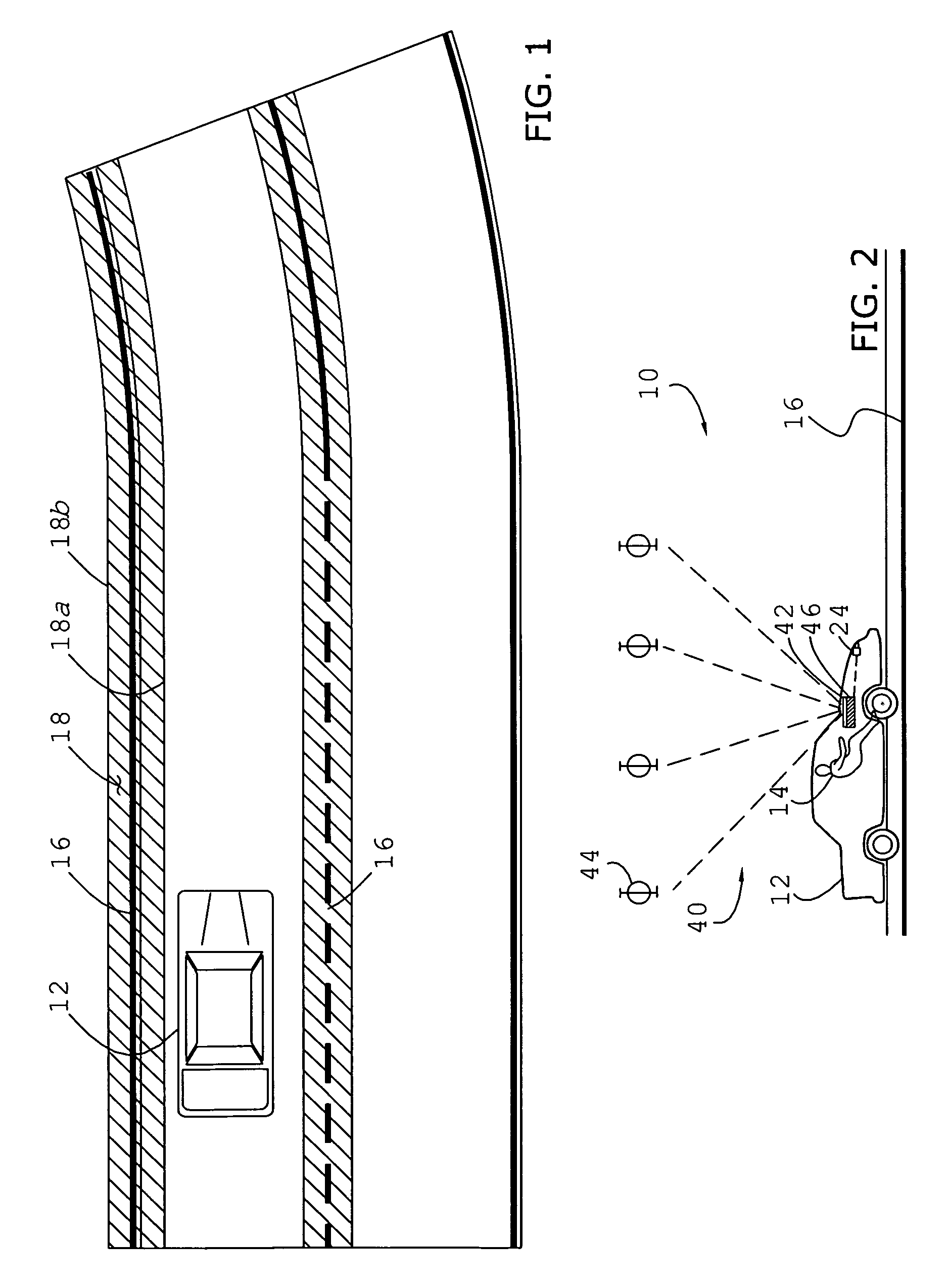
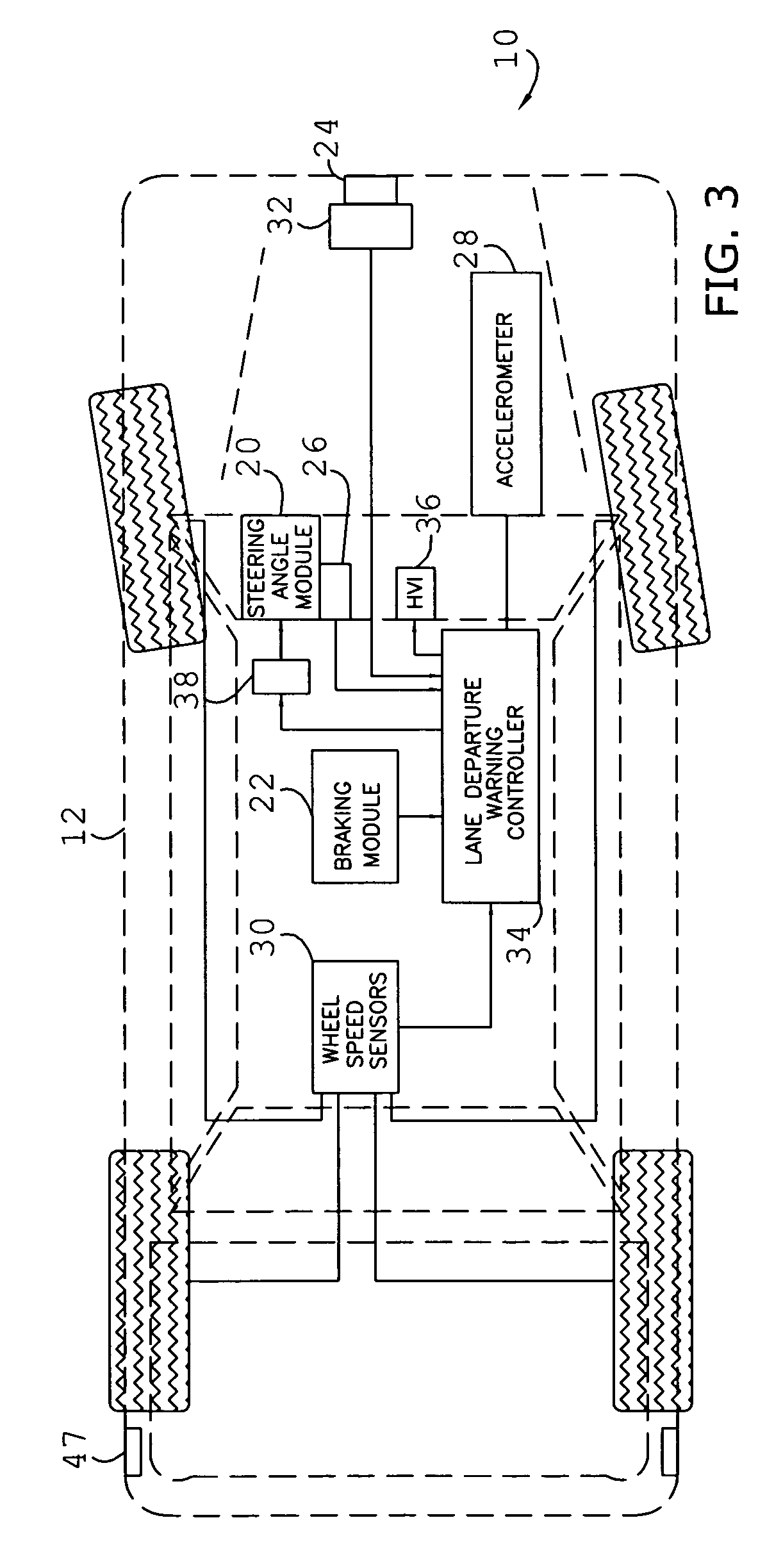
[0031]The present invention concerns an improved lane departure warning and / or lane change assist system 10 adapted for use with a host vehicle 12 traveling within a lane (e.g., of a thoroughfare or road), and by a human operator 14 (FIGS. 1 and 2), wherein the lane may be delineated by at least one lane-marking 16. The system 10 is described and illustrated herein with respect to an automobile, however, it is certainly within the ambit of the present invention to utilize the system 10 with other lane-based transportation machines, such as boats and airplanes taxiing on runways. As used herein, the term “lane-marking” includes visible elements such as highly reflective paint or thermoplastic stripes (whether in continuous or dashed line-type), curbs, medians, reflectors, and otherwise distinguishable edges of pavement, or invisible elements embedded under pavement such as magnetic elements. The system 10 is configured to detect the position of the vehicle 12 relative to a lane marki...


PUM


Abstract

A lane change assist and/or lane departure warning system adapted for use with a vehicle having a module engaged by an operator, wherein the vehicle travels within a lane, and the system includes a steering wheel sensor, at least one sensor operable to detect a lane-marking or an approaching object in adjacent lanes in the direction of host vehicle travel, a warning device including an active material element engaged with the module, and a controller communicatively coupled to the sensor and device and configured to determine a spatial relationship between the vehicle and the lane-marking or approaching object in the direction of host vehicle travel, compare the relationship to a threshold, transmit an activation signal to the element when the relationship exceeds the threshold or when an object is detected and the wheel sensor indicates a turn towards the object, and generate an alert by activating the element.

Description

BACKGROUND OF THE INVENTION[0001]1. Technical Field[0002]The present invention relates to lane departure warning and lane change assist systems adapted for use with a vehicle, and more particularly, to a lane departure warning and lane change assist system that utilizes active material activation, and more preferably, utilizes a Magneto-Rheological Hydraulic Power Steering (MR-HPS) system to effect warning.[0003]2. Background Art[0004]Lane departure warning and lane change assist (LDW / LCA) systems have been developed to assist operators (i.e. drivers) in maintaining proper lane alignment by alerting the operator to a possible unintentional lane departure and / or autonomously acting to keep the vehicle within the lane. Unlike scarifications and other measures commonly found on thoroughfare shoulders that alert the operator only after he or she has traversed the lane-marking, LDW systems provide timely warnings prior to lane departure. Lane change assist systems warn the driver of an a...

Claims


Application Information

Patent Timeline
Patent Type & Authority Applications(United States)
IPC IPC(8): B60Q1/00
CPCB60Q9/00B62D15/029B62D15/025B60T2201/082
Inventor LITKOUHI, BAKHTIAR BRIAN
Owner GM GLOBAL TECH OPERATIONS LLC
Why Eureka
Try Eureka