Liquid crystal display device

a liquid crystal display and display device technology, applied in the direction of instruments, lighting and heating apparatus, optical elements, etc., can solve the problems of difficult reduction of the thickness of the liquid crystal display device, deviation of the angle of radiating lights, and difficulty in uniform surface brightness, so as to facilitate uniform surface brightness of edge-light-type backlights, reduce the number of parts of edge-light-type backlights, and improve the effect of surface brightness

Active Publication Date: 2009-11-19
PANASONIC LIQUID CRYSTAL DISPLAY CO LTD
View PDF15 Cites 44 Cited by
  • Summary
  • Abstract
  • Description
  • Claims
  • Application Information

AI Technical Summary

Benefits of technology

[0028]According to the liquid crystal display device of the present invention, it is possible to easily make surface brightness of an edge-light-type backlight uniform.
[0029]Further, according to the liquid crystal display device of the present invention, the number of parts of the edge-light-type backlight can be decreased and, at the same time, the surface brightness of the backlight can be made uniform.

Problems solved by technology

Accordingly, it is difficult for the backlight which uses the light emitting diodes to uniformly radiate light in the vicinity of the light incident surface of the light guide plate thus giving rise to a drawback that it is difficult to make the surface brightness uniform.
However, such a light guide plate has a drawback that angles of radiating lights are deviated.
Accordingly, a liquid crystal display device which is provided with the conventional edge-light-type backlight has a drawback that the reduction of thickness of the liquid crystal display device is difficult or a drawback that a manufacturing cost of the liquid crystal display device is pushed up.

Method used


Image

  • Liquid crystal display device
  • Liquid crystal display device
  • Liquid crystal display device

Examples


Embodiment Construction

[0054]Hereinafter, the present invention is explained in detail based on preferred embodiments in conjunction with drawings.

[0055]Here, in all drawings for explaining the embodiment, parts having identical functions are given same numerals and their repeated explanation is omitted.

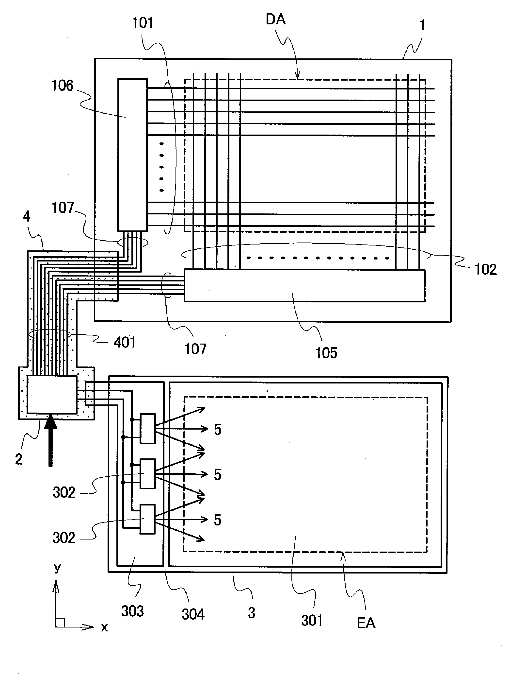
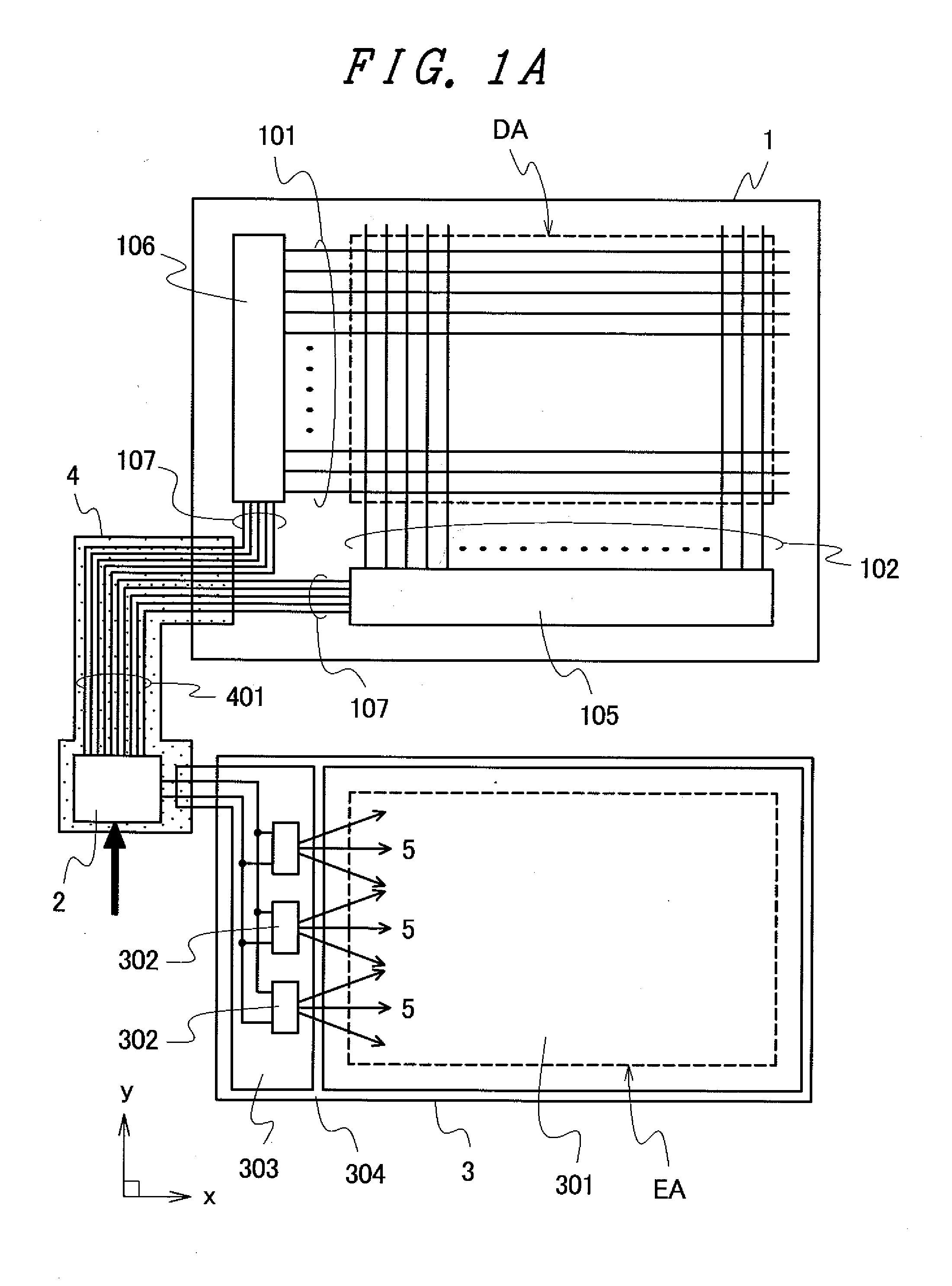
[0056]FIG. 1A to FIG. 1F are schematic views showing one example of the schematic constitution of a liquid crystal display device according to the present invention.

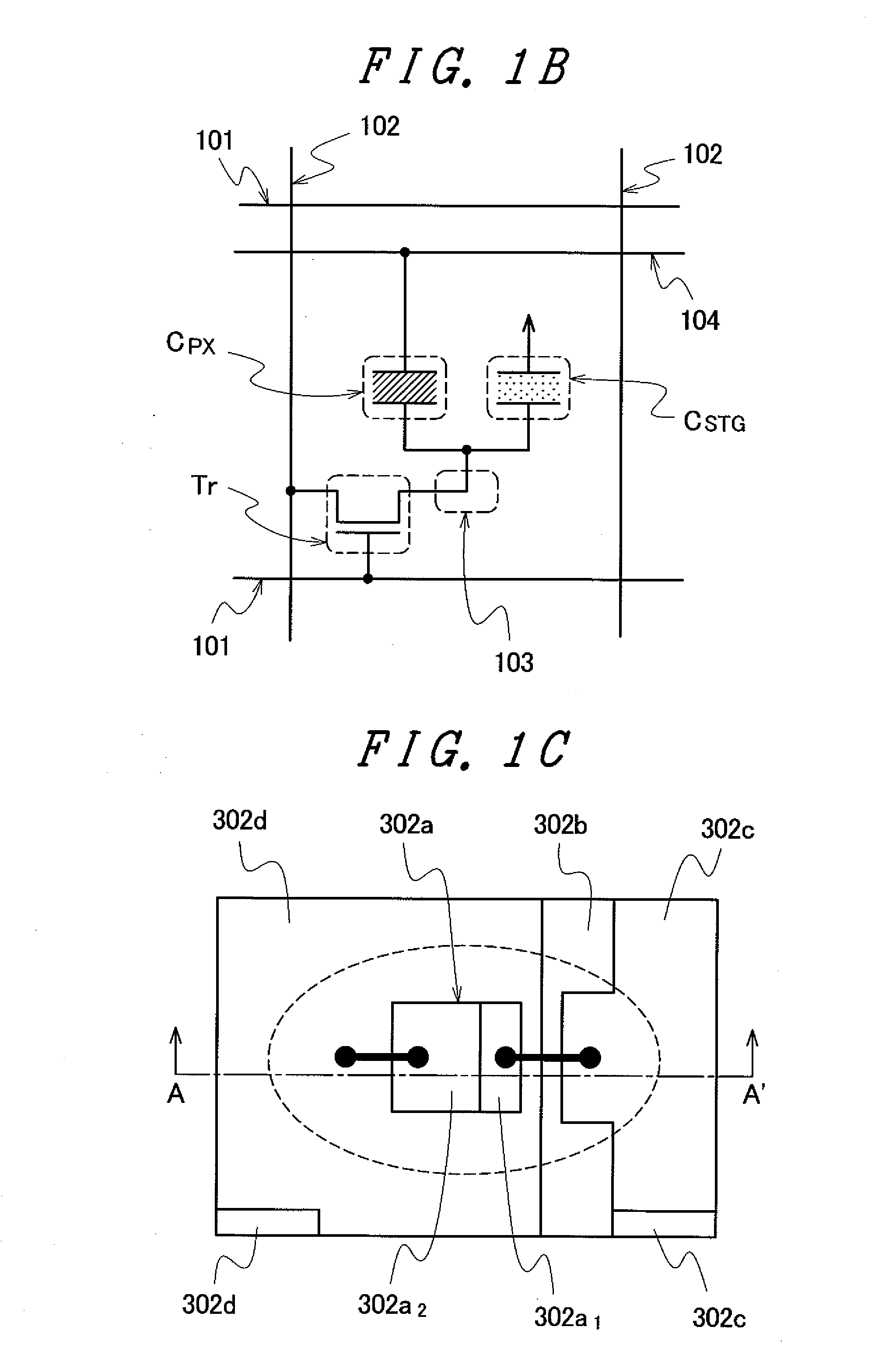
[0057]FIG. 1A is a schematic functional block diagram showing one example of the schematic constitution of an essential part of a liquid crystal display device. FIG. 1B is a schematic circuit diagram showing one example of the circuit constitution of one pixel of the liquid crystal display panel, FIG. 1C is a schematic plan view showing one example of the schematic constitution of a light emitting diode. FIG. 1D is a schematic cross-sectional view showing one example of the cross-sectional constitution of the light emitting diode taken along a ...


PUM

PropertyMeasurementUnit
refractive indexaaaaaaaaaa
angleaaaaaaaaaa
DAaaaaaaaaaa

Abstract

A liquid crystal display device which can make the surface brightness of an edge-light-type backlight uniform is provided. The liquid crystal display device includes a liquid crystal display panel and a backlight which radiates light to the liquid crystal display panel. The backlight includes a light guide plate which is arranged on a back side of the liquid crystal display panel, a light source arranged on an outer peripheral portion of a first main surface of the light guide plate which faces the liquid crystal display panel in an opposed manner, and a reflection sheet which is arranged on a back side of the light guide plate as viewed from the liquid crystal display panel. The light guide plate is made of a transparent resin having a refractive index of 1.53 or less. On a surface of the light guide plate opposite to the first main surface, a second main surface which is substantially parallel to the first main surface and a plurality of inclined surfaces which are inclined at a preset angle with respect to the second main surface are formed. An angle of the inclined surface positioned near a position at which light from the light source is incident and an angle of the inclined surface positioned remote from the position at which the light from the light source from the light source is incident differ from each other.

Description

CROSS-REFERENCE TO RELATED APPLICATION[0001]The present application claims priority from Japanese application JP 2008-127301 filed on May 14, 2008, the content of which is hereby incorporated by reference into this application.BACKGROUND OF THE INVENTION[0002]1. Field of the Invention[0003]The present invention relates to a liquid crystal display device, and more particularly to a liquid crystal display device having a backlight which includes a light guide plate and light emitting diodes.[0004]2. Background Art[0005]Conventionally, the liquid crystal display device has been used as a display part of portable electronic equipment, for example, because of a reduced thickness, a reduced weight and small electric power consumption.[0006]The liquid crystal display device is not of a self-luminous type and hence, a planar lighting device which is referred to as a backlight is arranged on a back surface of a liquid crystal display panel, for example. Although a conventional backlight uses...

Claims


Application Information

Patent Timeline
Patent Type & Authority Applications(United States)
IPC IPC(8): G02F1/13357
CPCG02F1/133615
Inventor SHIRAISHI, YASUHISATSURUOKA, ATSUSHITOBE, AKIYOSHINISHIZAWA, SHIGEKIYAJIMA, TOSHIHIRO
Owner PANASONIC LIQUID CRYSTAL DISPLAY CO LTD
Why Eureka
Try Eureka