Method and apparatus for positioning a subject in a ct scanner

a technology of computed tomography and positioning apparatus, which is applied in the field of method and apparatus for positioning a subject relative to a ct scanner, can solve the problems of time-consuming and inconvenience for both the technician operating the scanner and the patient, and the motorized lateral (left/right) alignment capability of ct scanners is not provided, and the support does not even provide a degree of freedom for left/right positioning

Active Publication Date: 2009-11-19
ARINETA
View PDF4 Cites 32 Cited by
  • Summary
  • Abstract
  • Description
  • Claims
  • Application Information

AI Technical Summary

Benefits of technology

[0020]According to some embodiments of the invention, the stereo image data are obtained in a single operation without having to move the subject and then repeat the process.
[00

Problems solved by technology

This can be time consuming and an inconvenience for both the technician operating the scanner and the patient.
Motorized lateral (left/right) alignment c

Method used


Image

  • Method and apparatus for positioning a subject in a ct scanner
  • Method and apparatus for positioning a subject in a ct scanner
  • Method and apparatus for positioning a subject in a ct scanner

Examples


Embodiment Construction

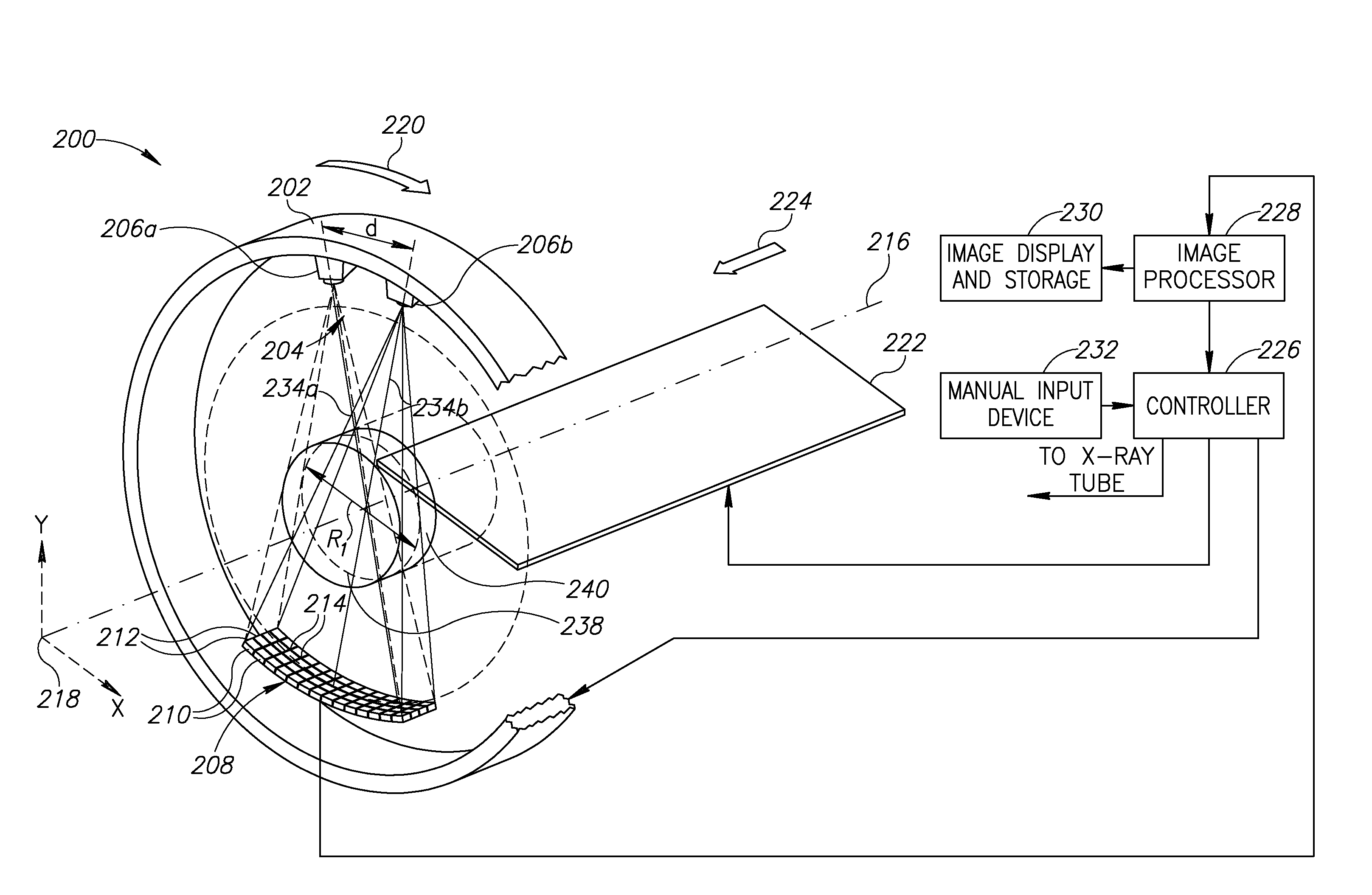
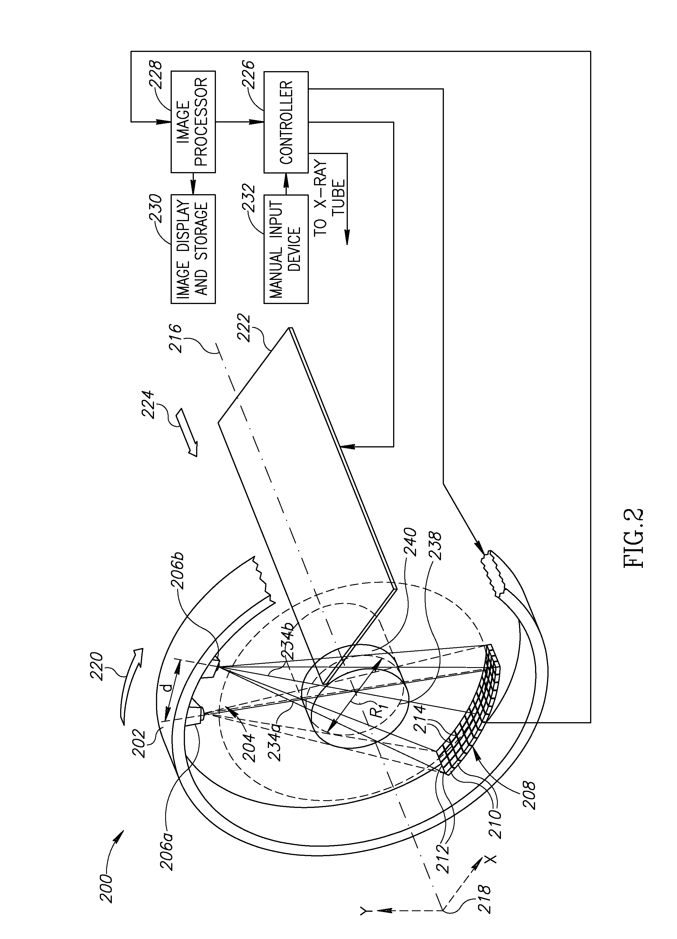
[0066]According to an embodiment of the invention, accurate positioning of a VOI of a subject in the VFOV of a CT scanner may be achieved with an arrangement as illustrated in FIG. 2. By way of a non-limiting example, the invention will be illustrated and described in the context of positioning a patient for cardiac imaging.

[0067]Referring to FIG. 2, CT unit 200 comprises a rotating support 202 on which is carried a dual beam X-ray source 204, shown schematically as being comprised of separate X-ray emitters 206a and 206b separated by a distance d in the direction of rotation 220 of rotor 202. A detector array 208 comprised of a plurality of rows 210 and columns 212 of X-ray detector elements 214 is supported by rotor 202 and positioned to intercept X-ray beams 234a and 234b provided by source 204 after the beams pass through a subject on support platform 222. Optionally, detector array 208 may be configured to provide greater resolution in its central portion than in the outer rows...


PUM


Abstract

An apparatus and method for optimally positioning a region of interest of a subject for imaging by a CT scanner. The scanner provides a source of one or more X-ray beams, at least one of which is used for acquiring a CT image of the subject, a movable support for the subject, and a controller that controls the X-ray source. To position the region of interest of the subject, the controller operates to illuminate the subject with X-rays to acquire stereo image data for the region of interest and controls the position of the support responsive to the stereo image data.

Description

FIELD OF THE INVENTION[0001]The present invention relates to computed tomography (CT) X-ray imaging and more particularly to a method and apparatus for positioning a subject relative to a CT scanner.BACKGROUND OF THE INVENTION[0002]In CT imaging, cross sectional axial images or slices of a volume of interest (VOI), for example, of a patient's body or, more generally, of an object under inspection, are created by computer processing of X-ray attenuation data acquired at multiple view angles around an axis of rotation.[0003]FIG. 1 is a schematic illustration of some basic features of a typical CT scanner 100 used for medical imaging. CT scanner 100 comprises a support rotor 102 mounted on a gantry (not shown) that carries an X-ray source 104 and a detector array 106, the latter being comprised of a plurality of rows 108 and columns 110 of closely spaced X-ray detector elements 112. Support rotor 102 is arranged for rotation in a direction indicated by an arrow 116 around a rotational ...

Claims


Application Information

Patent Timeline
IPC IPC(8): A61B6/00
CPCA61B6/022A61B6/035A61B6/04A61B6/08A61B6/4028A61B6/463A61B6/488A61B6/504A61B6/541A61B6/4007
Inventor BRADA, RAFAELDAFNI, EHUD
Owner ARINETA
Why Eureka
Try Eureka