Optical fiber sensor

a technology of optical fiber and sensor, applied in the direction of instruments, optical elements, force/torque/work measurement apparatus, etc., can solve the problems of difficult for the optical fiber sensor to detect the applied stress accurately, the object is likely to fall off the manipulator, and the object is damaged. , to achieve the effect of high durability and reliability

Inactive Publication Date: 2009-11-19
HONDA MOTOR CO LTD
View PDF4 Cites 18 Cited by
  • Summary
  • Abstract
  • Description
  • Claims
  • Application Information

AI Technical Summary

Benefits of technology

[0012]It is a general object of the present invention to provide an optical fiber sensor which is highly durable and reliable.

Problems solved by technology

At this time, if the manipulator applies excessive gripping forces to the object, then the object tends to be damaged.
Conversely, if the manipulator fails to apply sufficient gripping forces to the object, then the object is likely to fall off the manipulator.
However, the optical fiber sensor disclosed in Japanese Laid-Open Patent Publication No. 2002-131023 and Japanese Laid-Open Patent Publication No. 2002-071323 is problematic in that if the object gripped by the manipulator has a different shape or contacts the optical fiber at a different position, then a different stress distribution is produced on the gratings, making it difficult for the optical fiber sensor to detect the applied stress accurately.
Therefore, it is not easy to determine the exact magnitude of the applied stress, or stated otherwise, to achieve a sufficiently high level of measurement accuracy.

Method used


Image

  • Optical fiber sensor
  • Optical fiber sensor
  • Optical fiber sensor

Examples


first embodiment

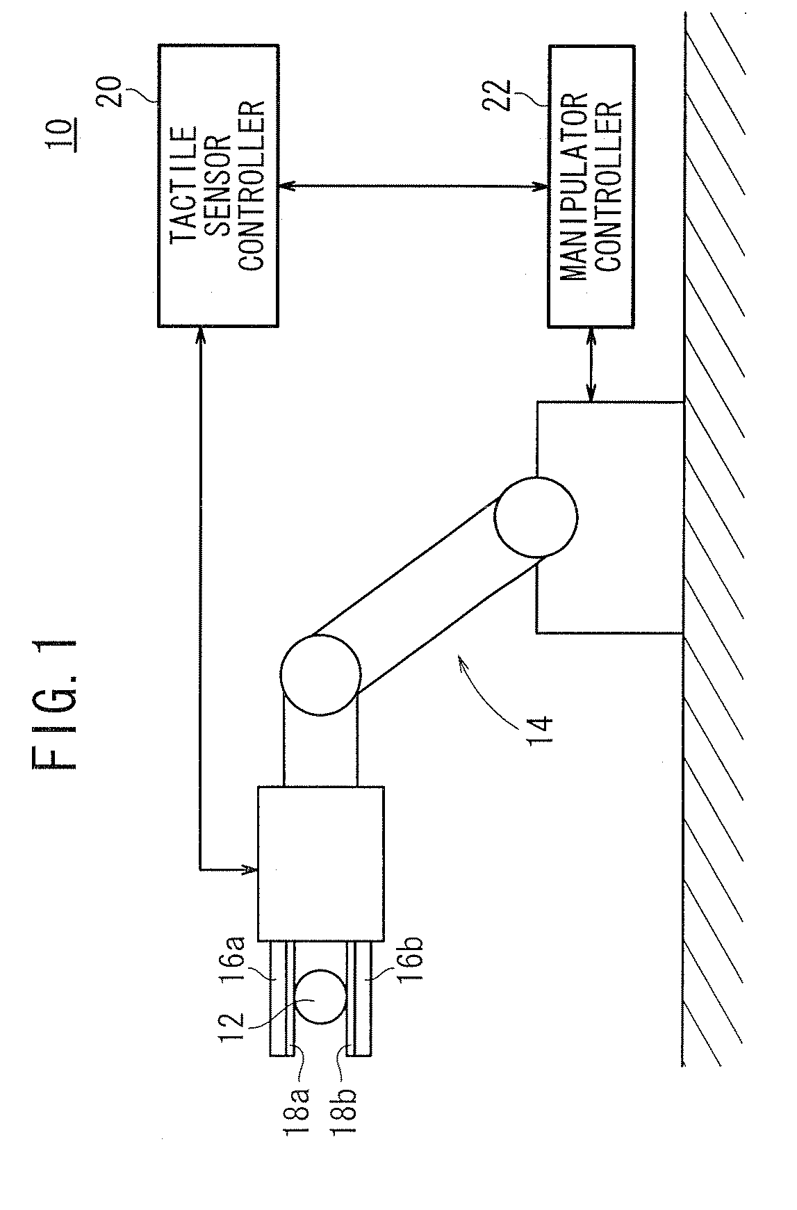
[0063]FIG. 1 schematically shows, partly in block form, a robot system 10 incorporating an optical fiber sensor (also hereinafter referred to as “tactile sensor”) according to the present invention. As shown in FIG. 1, the robot system 10 comprises a manipulator 14 for gripping and handling an object 12, a pair of tactile sensors 18a, 18b disposed respectively on hands 16a, 16b of the manipulator 14 for detecting a gripped state of the object 12 gripped by the hands 16a, 16b while being held in contact with the object 12, a tactile sensor controller 20 for controlling the tactile sensors 18a, 18b to acquire shearing stresses and a perpendicular stress which serve as information representative of the gripped state of the object 12, and a manipulator controller 22 for controlling the manipulator 14 based on the shearing stresses and the perpendicular stress that have been acquired by the tactile sensor controller 20.

[0064]A slippage of the object 12 with respect to the hands 16a, 16b ...

second embodiment

[0081]As shown in FIG. 12, each of the tactile sensors 18a, 18b may comprise a stacked assembly of the X-direction shearing stress sensor section 32, the Y-direction shearing stress sensor section 34, and the Z-direction stress sensor section 36. Alternatively, according to the present invention as shown in FIG. 13, each of the tactile sensors 18a, 18b may comprise a stacked assembly of a shearing stress sensor section 35 which is an integral combination of the X-direction shearing stress sensor section 32 and the Y-direction shearing stress sensor section 34, and the Z-direction stress sensor section 36.

[0082]As the tactile sensors 18a, 18b are in the form of the flexible sheet bodies of the X-direction shearing stress sensor section 32, the Y-direction shearing stress sensor section 34, and the Z-direction stress sensor section 36, the tactile sensors 18a, 18b can be installed on the surfaces of the hands 16a, 16b which may be of any desired shapes.

[0083]The X-direction shearing s...

third embodiment

[0093]An optical fiber sensor according to the present invention will be described in detail below.

[0094]FIG. 15 schematically shows, partly in block form, a robot system 110 incorporating the optical fiber sensor according to the third embodiment of the present invention. As shown in FIG. 15, the robot system 110 comprises a manipulator 14 for gripping and handling an object 12, a pair of optical fiber sensors 118a, 118b disposed respectively on hands 16a, 16b of the manipulator 14 for detecting a gripped state of the object 12 gripped by the hands 16a, 16b while being held in contact with the object 12, an optical fiber sensor controller 20 for controlling the optical fiber sensors 118a, 118b to acquire shearing stresses and a perpendicular stress which serve as information representative of the gripped state of the object 12, and a manipulator controller 22 for controlling the manipulator 14 based on the shearing stresses and the perpendicular stress that have been acquired by th...


PUM


Abstract

An optical fiber sensor which functions as a tactile sensor includes a plurality of shearing stress sensor sections including respective optical fibers and a plurality of gratings for reflecting light beams having predetermined wavelengths. The gratings are disposed in the optical fibers and arrayed along a plane parallel to the direction in which a shearing stress is applied from an object to the shearing stress sensor sections. The sensor also includes a perpendicular stress sensor section including an optical fiber and a plurality of gratings for reflecting a light beam having a predetermined wavelength. The gratings are disposed in the optical fiber and arrayed along a plane parallel to the direction in which a perpendicular stress is applied from the object to the perpendicular stress sensor section. Preferably, stress direction converting means such as elastic members for converting the direction of an applied stress are mounted on the optical fibers.

Description

BACKGROUND OF THE INVENTION[0001]1. Field of the Invention[0002]The present invention relates to an optical fiber sensor for detecting stresses with an optical fiber which incorporates therein a plurality of gratings for reflecting light beams having certain wavelengths.[0003]2. Description of the Related Art[0004]In some manipulator applications, the manipulator grips an object and performs a certain type of work on the object. At this time, if the manipulator applies excessive gripping forces to the object, then the object tends to be damaged. Conversely, if the manipulator fails to apply sufficient gripping forces to the object, then the object is likely to fall off the manipulator.[0005]To prevent damage to the object or hold the object securely, it has been attempted in the art to combine the manipulator with a sensor for detecting the gripped state of the object that is being gripped by the manipulator. One type of such a sensor comprises a tactile sensor for detecting a perpe...

Claims


Application Information

Patent Timeline
Patent Type & Authority Applications(United States)
IPC IPC(8): G02B6/00
CPCG01B11/18G01L5/226G01L1/246G01B11/165G01L5/009
Inventor KUNIGAMI, MASAKIFUEKI, NOBUHIROKOBAYASHI, MASATOSHIFURUKAWA, MAKOTO
Owner HONDA MOTOR CO LTD
Why Eureka
Try Eureka