
Baking apparatus, baking mehod and method of reducing gap width

Active Publication Date: 2009-11-19
MACRONIX INT CO LTD
View PDF3 Cites 8 Cited by
  • Summary
  • Abstract
  • Description
  • Claims
  • Application Information

AI Technical Summary

Benefits of technology

[0008]The present invention provides a baking apparatus which can provide a uniform temperature distribution to a substrate, so that the decrease in the yield and the performance of a device resulted from an uneven baking temperature can be avoided.
[0009]The present invention further provides a baking method to maintain the baking temperature to be more even so as to increase the uniformity of critical dimensions.
[0010]The present invention also provides a method of reducing a gap width to reduce critical dimensions more evenly without replacing any existing manufacturing equipment in the fabrication.
[0022]The present invention also provides a method of reducing a gap width. First, a substrate is provided, and the substrate has a patterned photoresist layer thereon, wherein the patterned photoresist layer has a plurality of patterns. Thereafter, a dynamic baking is preformed so that the patterned photoresist layer flows to the gaps between the patterns, wherein the substrate is disposed over a hot plate, and the hot plate maintains static while the substrate keeps rotating.
[0028]In this invention, a dynamic baking can be conducted with the baking apparatus, in which a hot plate maintains static while the substrate keeps rotating. The baking apparatus is applicable to the baking method so that the baking temperature is more even and the uniformity of critical dimensions is enhanced. The baking apparatus is also be applicable to the method of reducing a gap width so that critical dimensions can be reduced uniformly to the desired dimensions without the requisite of replacing any existing manufacturing equipment in the fabrication.

Problems solved by technology

In addition, raising the line width resolution in the photolithographic process beyond 65 nm in the current state of technology is rather difficult, unless a light source having a shorter wavelength and a corresponding photoresist are used.
However, it is very costly to replace existing machines entirely with new machines for this purpose.

Method used


Image

  • Baking apparatus, baking mehod and method of reducing gap width
  • Baking apparatus, baking mehod and method of reducing gap width
  • Baking apparatus, baking mehod and method of reducing gap width

Examples


Embodiment Construction

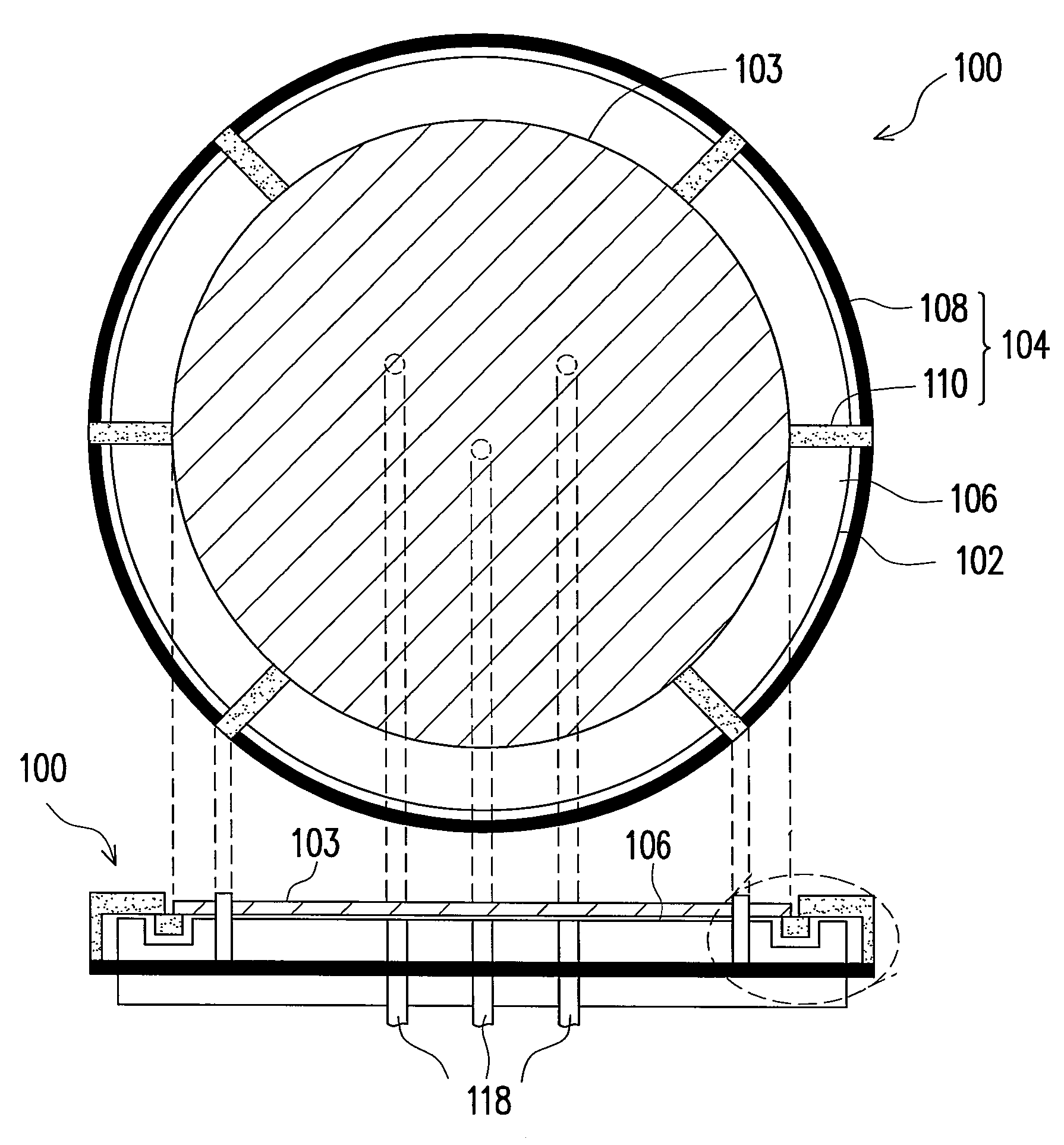
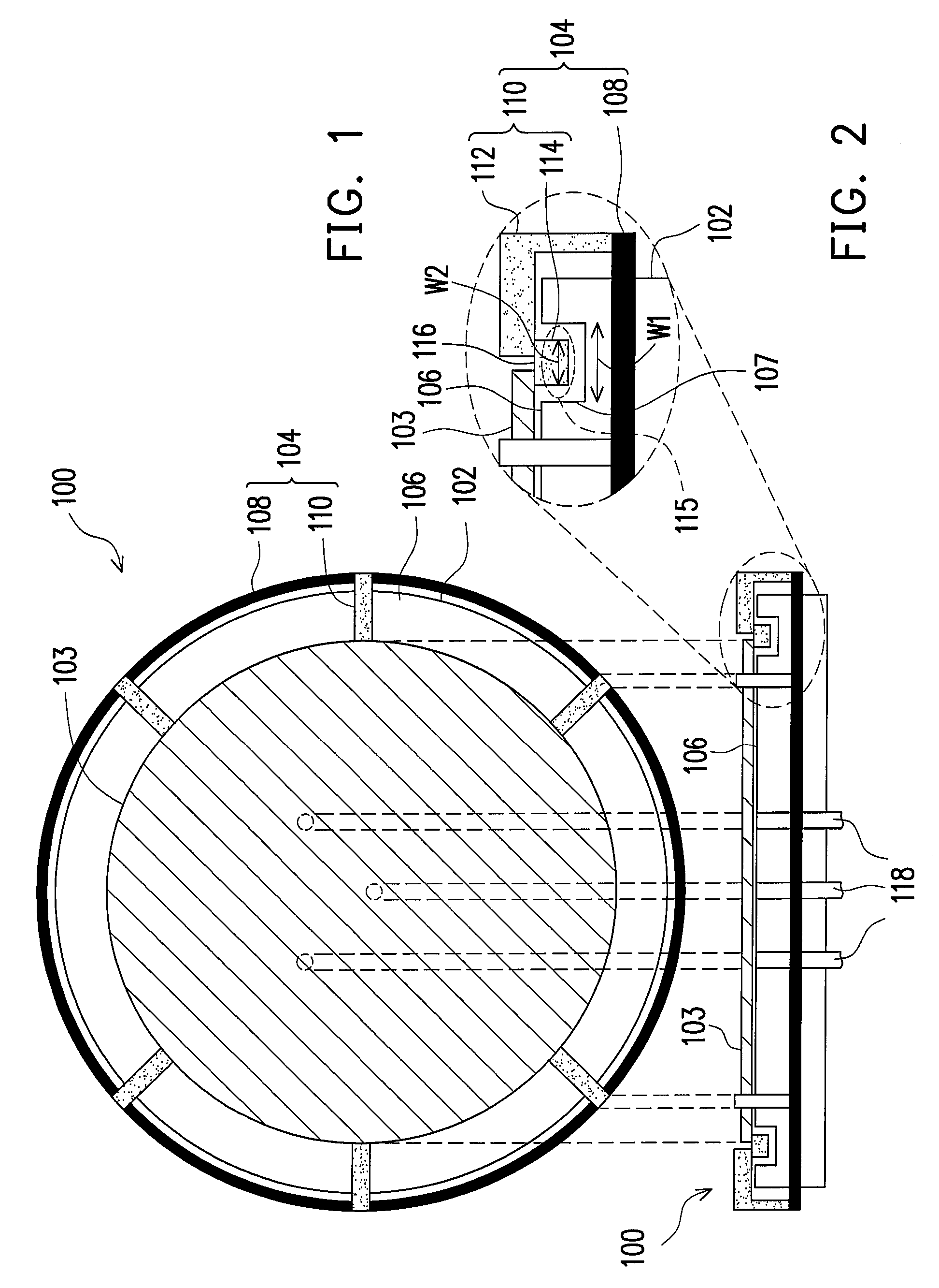
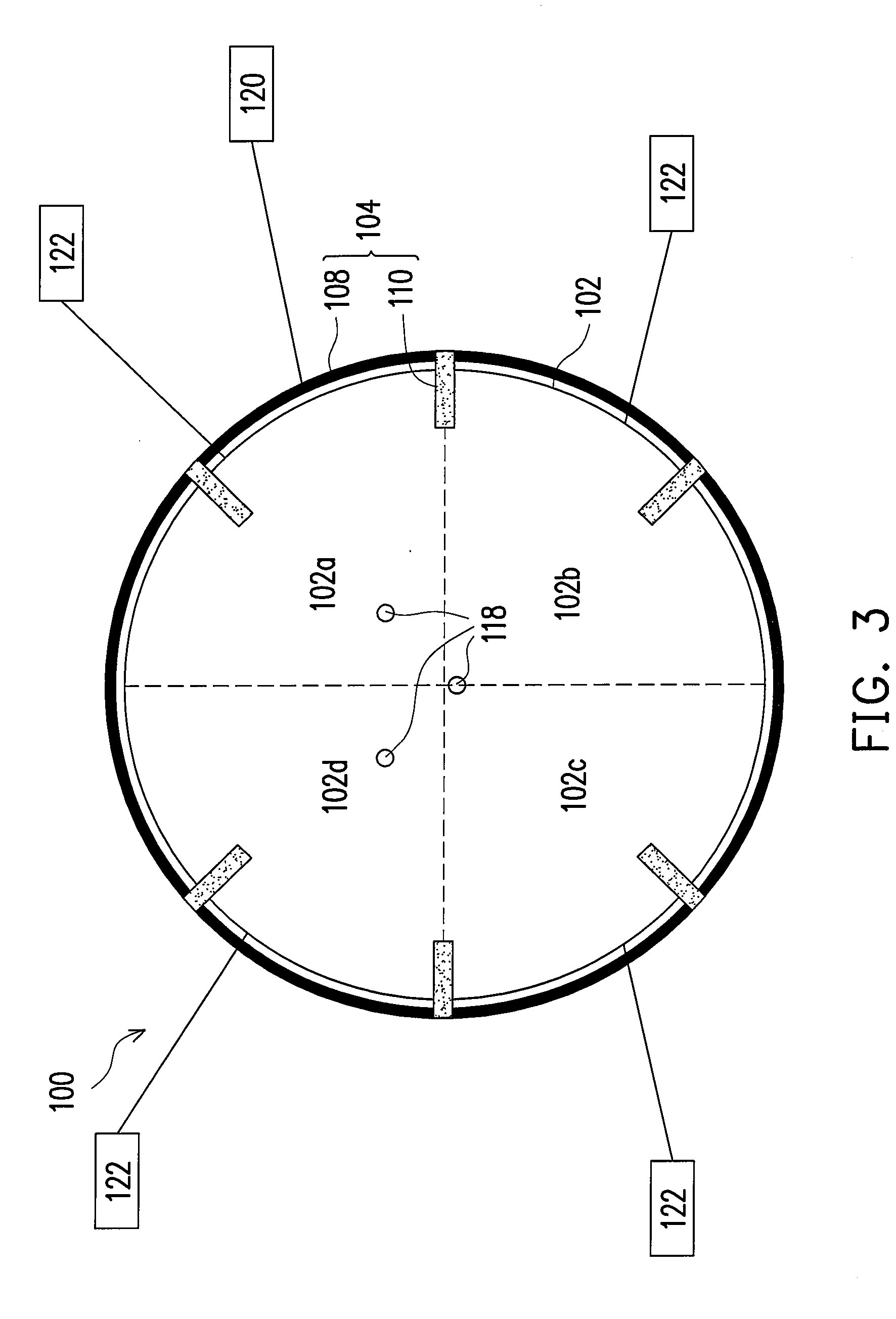
[0037]FIG. 1 schematically illustrates a top view of a baking apparatus with a substrate thereon according to an embodiment of the present invention. FIG. 2 is a side view of FIG. 1, and the right top side of FIG. 2 is a partially enlarged view. FIG. 3 schematically illustrates a top view of a baking apparatus according to an embodiment of the present invention.

[0038]Referring to FIG. 1, a baking apparatus 100 includes a hot plate 102 and a substrate rotation member 104. The hot plate 102 is for heating a substrate 103. The rotation member 104 is for rotating the substrate 103 disposed over the hot plate 102.

[0039]The hot plate 102 has a heating surface 106. The substrate rotation member 104 includes a rotation ring 108 and a plurality of support arms 100. The rotation ring 108 is configured to surround the hot plate 102. The support arms 110 are disposed over the heating surface 106 of the hot plate 102 and respectively connect to the rotation ring 108. Each of the support arms 110...


PUM

PropertyMeasurementUnit
Temperatureaaaaaaaaaa
Lengthaaaaaaaaaa

Abstract

A baking apparatus including a hot plate and a substrate rotation member is provided. The hot plate has a heating surface. The substrate rotation member includes a rotation ring and a plurality of support arms. The rotation ring is configured to surround the hot plate. The support arms are disposed over the heating surface of the hot plate. Each of the support arms includes a connection part and a support part, wherein the connection part is configured to connect the rotation ring and the support part, and a supporting surface of the support part for supporting the substrate is higher than the heating surface of the hot plate.

Description

BACKGROUND OF THE INVENTION[0001]1. Field of Invention[0002]The present invention relates to a semiconductor apparatus and a semiconductor fabrication method. More particularly, the present invention relates to a baking apparatus, a baking method and a method of reducing a gap width.[0003]2. Description of Related Art[0004]Due to the rapid development of integrated circuits, minimizing the device dimension and increasing the integration level have become the mainstream in semiconductor industry, and the key technology is in photolithography.[0005]In the photolithography process, it is known that the uniformity of critical dimensions is affected by the baking temperature distribution. Usually a line width of 5 nm is changed as the temperature is shifted by each degree in Centigrade (° C.). A baking apparatus generally includes a plurality of heating units so as to control the temperature variation within ±0.2° C. However, it is inevitable that when a substrate is heated in the baking...

Claims


Application Information

Patent Timeline
IPC IPC(8): H01L21/30H05B3/68
CPCH05B3/68H01L21/0273
Inventor YANG, CHIN-CHENG
Owner MACRONIX INT CO LTD
Learn More