Buoyant plant habitat and process for its manufacture

a plant habitat and plant technology, applied in the field of floating plant habitats, can solve the problems of damage to growing plants, insufficient buoyancy or large floating planters for human traffic, and the method of providing buoyancy is fragile, so as to achieve relatively rigid and buoyant walkways, the effect of maintaining buoyancy

Inactive Publication Date: 2009-11-26
FOUNTAINHEAD
View PDF67 Cites 22 Cited by
  • Summary
  • Abstract
  • Description
  • Claims
  • Application Information

AI Technical Summary

Benefits of technology

[0010]The purpose of a preferred embodiment of the invention is to utilize a fibrous non-woven polyester matrix in combination with injected buoyant (e.g., polyurethane) foam to form a floating island body. In other preferred embodiments, sprayed-on polymer coatings may optionally be applied to selected portions of the top surface of the island. The coatings may be used to provide ultraviolet (UV) protection for the buoyant foam to preserve buoyancy, to provide nesting zones for birds, to trap gases that can provide supplemental buoyancy, and to provide relatively rigid and buoyant walkways for human traffic.
[0011]One advantage of preferred embodiments of the invention is that the injected foam buoyancy units can be designed so as not to protrude significantly onto the top growing surface of the structure, thereby providing maximum surface area for plant establishment and growth, when such conditions are desirable. Moreover, the injected foam does not require cutouts within the matrix. It is preferably injected into the matrix and bonds to the matrix fibers, thereby eliminating the requirement for an additional manufacturing operation and providing maximum structural strength of the island body.
[0012]The floating island in accordance with this invention may be advantageously designed to be either flexible or rigid, depending on the application. The degree of flexibility can be determined by the diameter of the matrix fibers, the pattern of the injected foam units, and the thickness of the matrix. Flexibility enables preferred embodiments of the island to undulate with wave action. This undulation reduces the tendency for waves to wash over the island surface, thereby minimizing damage to plants. In addition, a flexible island dampens wave amplitude by absorbing and reflecting wave energy. Alternately, the island can be designed to be relatively rigid for applications such as boat docks or floating bridges, where rigidity is desirable for stability. Rigidity also is beneficial for distributing a concentrated top loads over a large surface area, thereby allowing the island to support a relatively heavy concentrated load while maintaining buoyancy over the entire surface area.

Problems solved by technology

This method of providing buoyancy tends to be fragile (e.g., subject to failure by impact from boats and pressure from freezing ice) and expensive.
Background art floating planters are not designed to be sufficiently large or buoyant to support human traffic.
Waves are likely to wash over the top of rigid planters, causing damage to growing plants.
Moreover, currently available floating planters have uniformly distributed buoyancy and are poorly suited for supporting relatively heavy concentrated loads such as batteries and pumps that may be useful for circulating or aerating water.
If the buoyancy of these structures is set to provide the ideal water level for young plants, then the water level may not be optimal when the plants grow and add additional negative buoyancy to the structure.
Currently available floating planters are not optimized for producing and / or trapping gases that can provide supplemental buoyancy for the structure.

Method used


Image

  • Buoyant plant habitat and process for its manufacture
  • Buoyant plant habitat and process for its manufacture
  • Buoyant plant habitat and process for its manufacture

Examples


Embodiment Construction

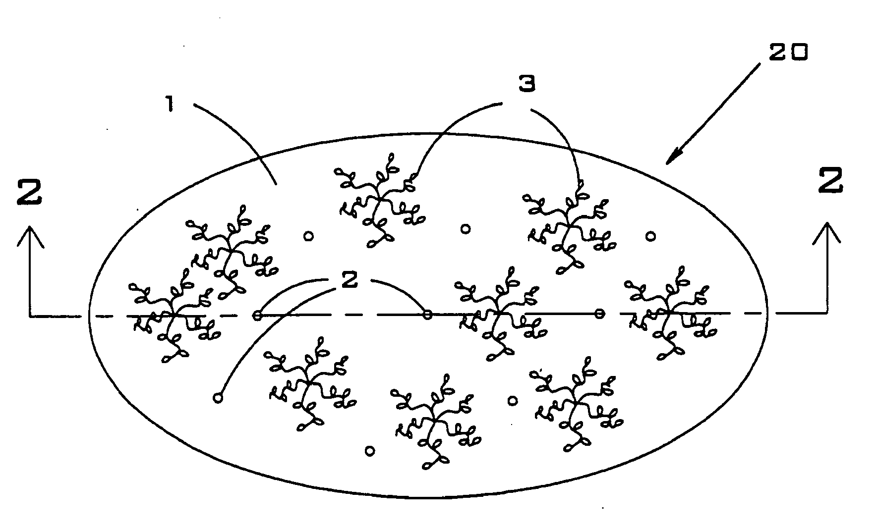
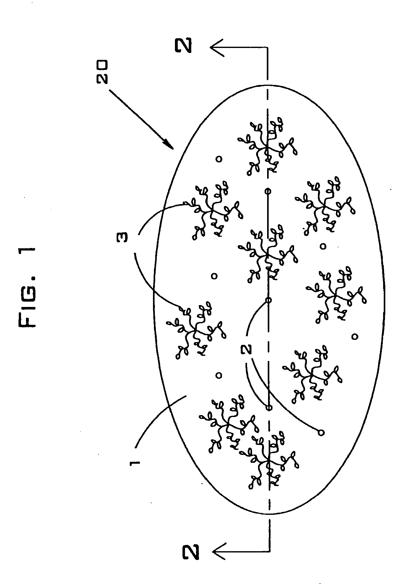
[0087]Referring to FIG. 1, a preferred embodiment of floating island or buoyant plant habitat 20 is presented. In this embodiment, floating island 20 comprising nonwoven matrix 1, buoyant polyurethane foam units 2 and plants 3. Preferably, buoyant units 2 are manufactured by injecting uncured liquid polyurethane resin under pressure through top surface 26 of porous matrix 1. The polyurethane resin is then allowed to expand and cure in place within matrix 1. The injection pressure, resin temperature, and injection shot volume of the foam injection machine (not shown) are preferably preset so as to provide the desired final volume of cured buoyant foam in each one of the buoyant units 2. In preferred embodiments, the polyurethane resin is injected through the top, sides, or bottom of the floating island 20, or through a combination of these surfaces, depending on the particular application of the island.

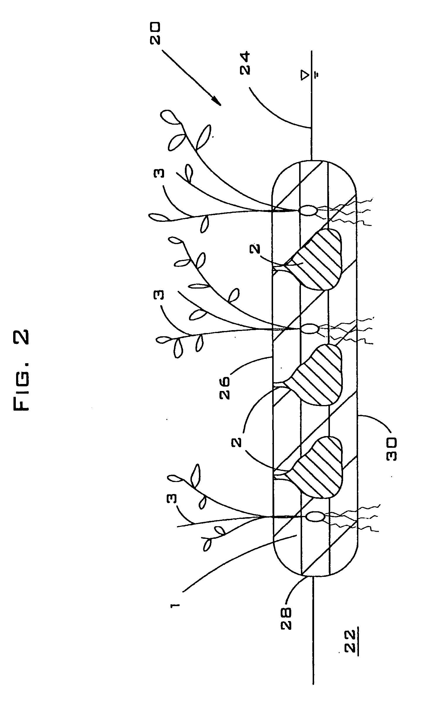
[0088]Referring to FIG. 2, a side (elevation) cross-sectional view of the embodime...


PUM

PropertyMeasurementUnit
diameteraaaaaaaaaa
pressureaaaaaaaaaa
densitiesaaaaaaaaaa

Abstract

A buoyant plant habitat and a process for manufacturing it. In one embodiment, the invention is a buoyant plant habitat comprising: a nonwoven matrix comprising fibers; and a plurality of buoyant foam units into said nonwoven matrix to produce a buoyant mass; wherein said buoyant foam units envelope a portion of said fibers. In another embodiment, the invention is a process for making a buoyant plant habitat comprising: providing a nonwoven matrix comprising fibers; and injecting a plurality of buoyant foam units into said nonwoven matrix. In another embodiment, the invention is a buoyant plant habitat comprising: a top layer of nonwoven matrix material; a bottom layer of nonwoven matrix material; a plurality of edge pieces of nonwoven matrix material that are attached by means of polymer plugs to said top layer and said bottom layer; and a plurality of closed-cell polymer foam pieces that are disposed between said layers.

Description

CROSS-REFERENCE TO RELATED APPLICATION[0001]This application claims priority back to U.S. Patent Application No. 60 / 820,341, filed on 25 Jul. 2006.BACKGROUND OF THE INVENTION[0002]This invention relates to floating plant habitats, In particular, the invention relates to a method for manufacturing a floating plant habitat that comprises a nonwoven matrix and a plurality of injected buoyant foam units.[0003]The background art is characterized by U.S. Pat. Nos. 5,224,292; 5,528,856; 5,766,474; 5,980,738; 6,086,755; and 6,555,219 and U.S. Patent Application Nos. 2003 / 0051398; 2003 / 0208954; 2005 / 0183331; the disclosures of which patents and patent applications are incorporated by reference as if fully set forth herein.[0004]Background art floating planters have four major deficiencies that are overcome in preferred embodiments of the present invention. Some background art planters are predominantly covered by materials that prevent or restrict plant growth. For example, the invention des...

Claims


Application Information

Patent Timeline
Patent Type & Authority Applications(United States)
IPC IPC(8): A01G9/02B29C44/42A01G31/02
CPCA01G9/00A01G9/28
Inventor KANIA, BRUCE G.STEWART, FRANK M.
Owner FOUNTAINHEAD
Why Eureka
Try Eureka