Component arrangement, combustion chamber arrangement and gas turbine

Inactive Publication Date: 2009-11-26
SIEMENS AG
View PDF5 Cites 24 Cited by
  • Summary
  • Abstract
  • Description
  • Claims
  • Application Information

AI Technical Summary

Benefits of technology

[0015]Furthermore, the groove may run around the component element toward which it is open. In this case, the pressure relief depression may extend along the entire side face of the groove and/or along the entire first side face (31a) of the holding element. Alternatively to this, a plurality of pressure relief depressions in the form of segments may extend along the entire side face of the groove and/or along the entire first side face of the holding element. The pressure relief depression may therefore, in other w

Problems solved by technology

If the ring height and/or the pressure difference are/is relatively high, this may lead to frictional forces which virtually block the holding ring in the guide groove.
The structural elements involved may in this case be overloaded, and this m

Method used


Image

  • Component arrangement, combustion chamber arrangement and gas turbine
  • Component arrangement, combustion chamber arrangement and gas turbine
  • Component arrangement, combustion chamber arrangement and gas turbine

Examples


Example

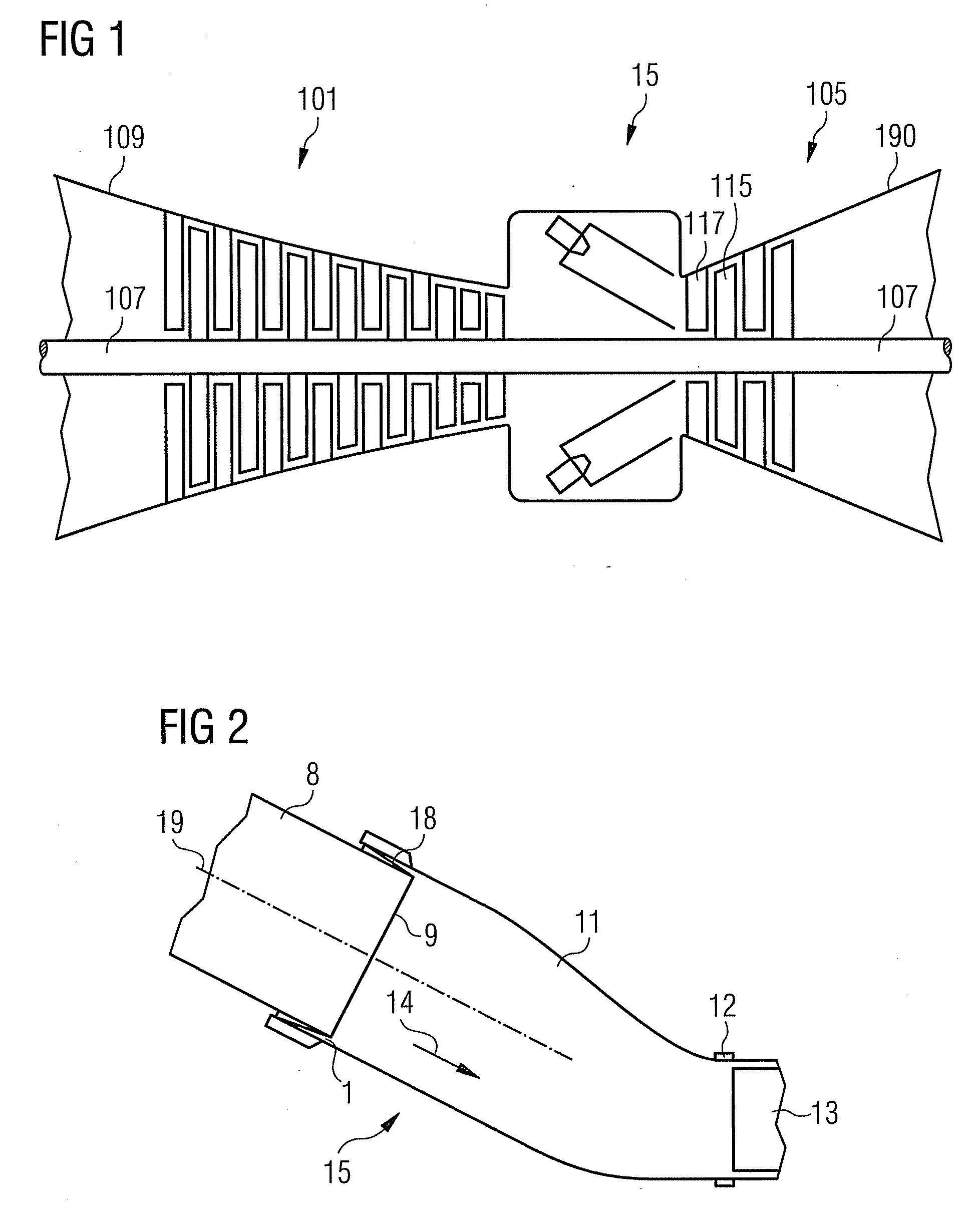
[0038]FIG. 1 shows diagrammatically a gas turbine. A gas turbine has inside it a rotor rotary-mounted about an axis of rotation and having a shaft 107, said rotor also being designated as a turbine rotor. An intake casing 109, a compressor 101, a plurality of combustion chamber arrangements 15, a turbine 105 and the exhaust gas casing 190 succeed one another along the rotor.

[0039]Each combustion chamber arrangement 15 communicates with an, for example, annular hot gas duct. There, a plurality of turbine stages connected in series form the turbine 105. Each turbine stage is formed from two blade rings. As seen in the direction of flow of a working medium, a guide blade row 117 is followed in the hot gas duct by a row formed from moving blades 115. The guide blades 117 are in this case fastened to an inner casing of a stator, whereas the moving blades 115 of a row are attached to the rotor, for example by means of a turbine disk. A generator or a working machine is coupled to the roto...


PUM


Abstract

A component arrangement is provided which includes two component elements with portions pushed one into the other, leaving a gap and arranged statically with respect to one another. The component arrangement also includes a sealing element sealing off the gap. One of the component elements has a groove which runs in the region of the gap to be sealed off and is open towards the other component element. The component that has the groove has a side face. The sealing element includes a holding element with a first side face and with a second side face and is arranged at least partially in the groove. The first side face of the holding element can be pushed against the side face of the groove by a pressure difference. The side face of the groove and/or the first side face of the holding element include/includes at least one pressure relief depression.

Description

CROSS REFERENCE TO RELATED APPLICATIONS[0001]This application claims priority of European Patent Office application No. 08009563.1 EP filed May 26, 2008, which is incorporated by reference herein in its entirety.FIELD OF INVENTION[0002]The present invention relates to a component arrangement and a combustion chamber arrangement with a sealing element. The invention relates, moreover, to a gas turbine.BACKGROUND OF INVENTION[0003]A combustion chamber, for example a combustion chamber of a gas turbine, often comprises various components which are partially pushed one into the other. In particular, the outlet of a flame tube and a transition element adjoining the flame tube are frequently pushed partially one into the other. The gap in this case typically occurring between the portions pushed one into the other has to be sealed off. This often takes place with the aid of clamping spring seals, but may also take place by means of brush seals.[0004]In the case where a brush seal, which c...

Claims


Application Information

Patent Timeline
IPC IPC(8): F02C7/20
CPCF23M2900/05002F23R2900/00012F23R3/60F23M2900/05005
Inventor CERNAY, CHRISTOPHTSCHIRREN, STEFAN
Owner SIEMENS AG
Why Eureka
Try Eureka