Quick temperature-equlizing heat-dissipating device

Active Publication Date: 2009-11-26
CHIN CHI TE
View PDF51 Cites 12 Cited by
  • Summary
  • Abstract
  • Description
  • Claims
  • Application Information

AI Technical Summary

Benefits of technology

[0007]The primary objective of the present invention is to provide a quick temperature-equalizing heat-dissipating device, which is structura

Problems solved by technology

More advanced chip indicates that there are more transistors on the integrated circuit, such that high heat and high power generated will result in high working temperature to reveal the faults resulted from various tiny physical flaws, like bridge fault.
Further, the high working temperature will enlarge the interconnect resistance and increase the line delay, such that the delay fault seems serious.
Besid

Method used


Image

  • Quick temperature-equlizing heat-dissipating device
  • Quick temperature-equlizing heat-dissipating device
  • Quick temperature-equlizing heat-dissipating device

Examples


Embodiment Construction

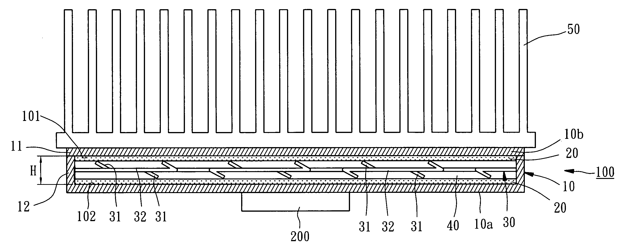
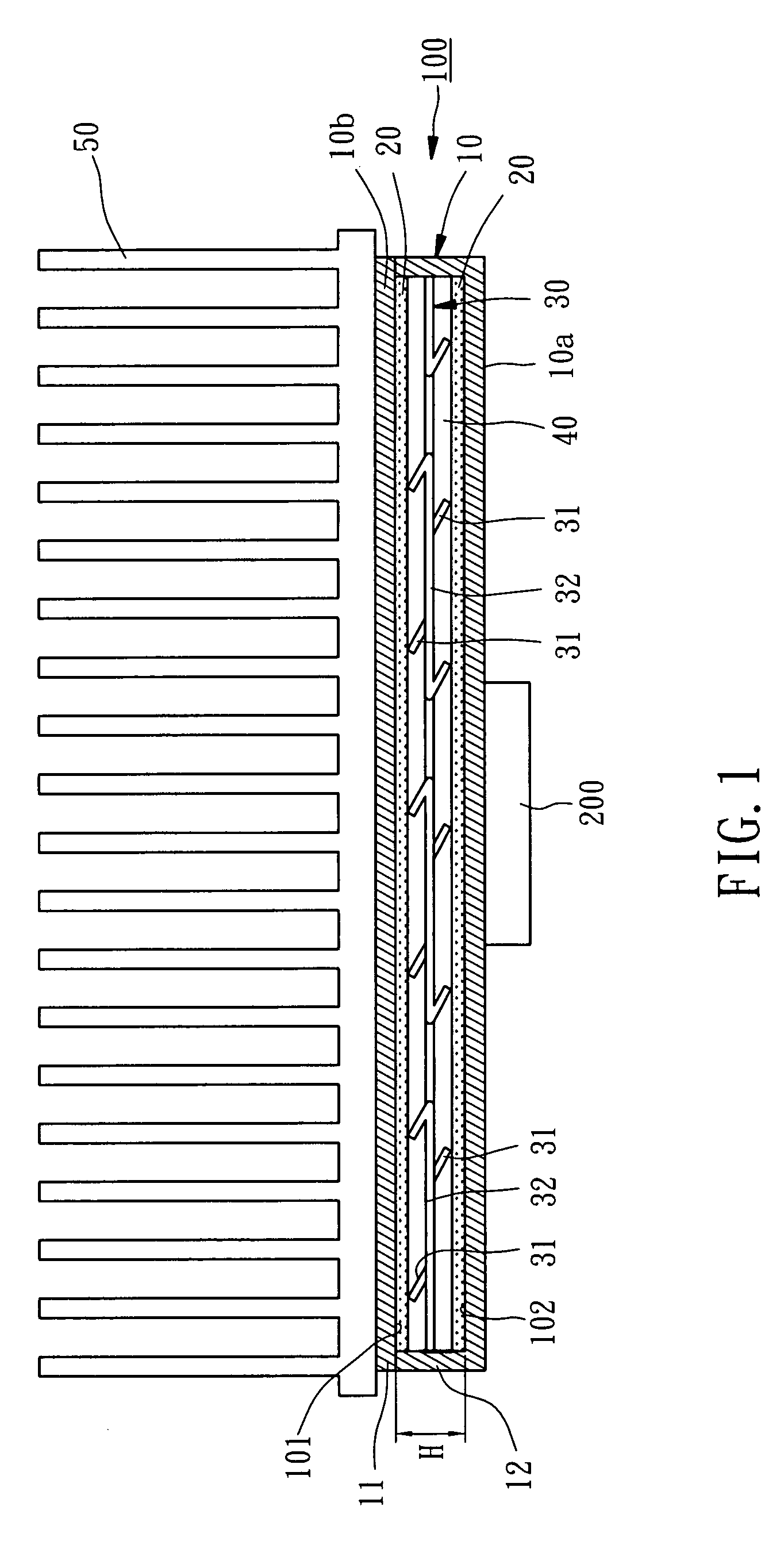
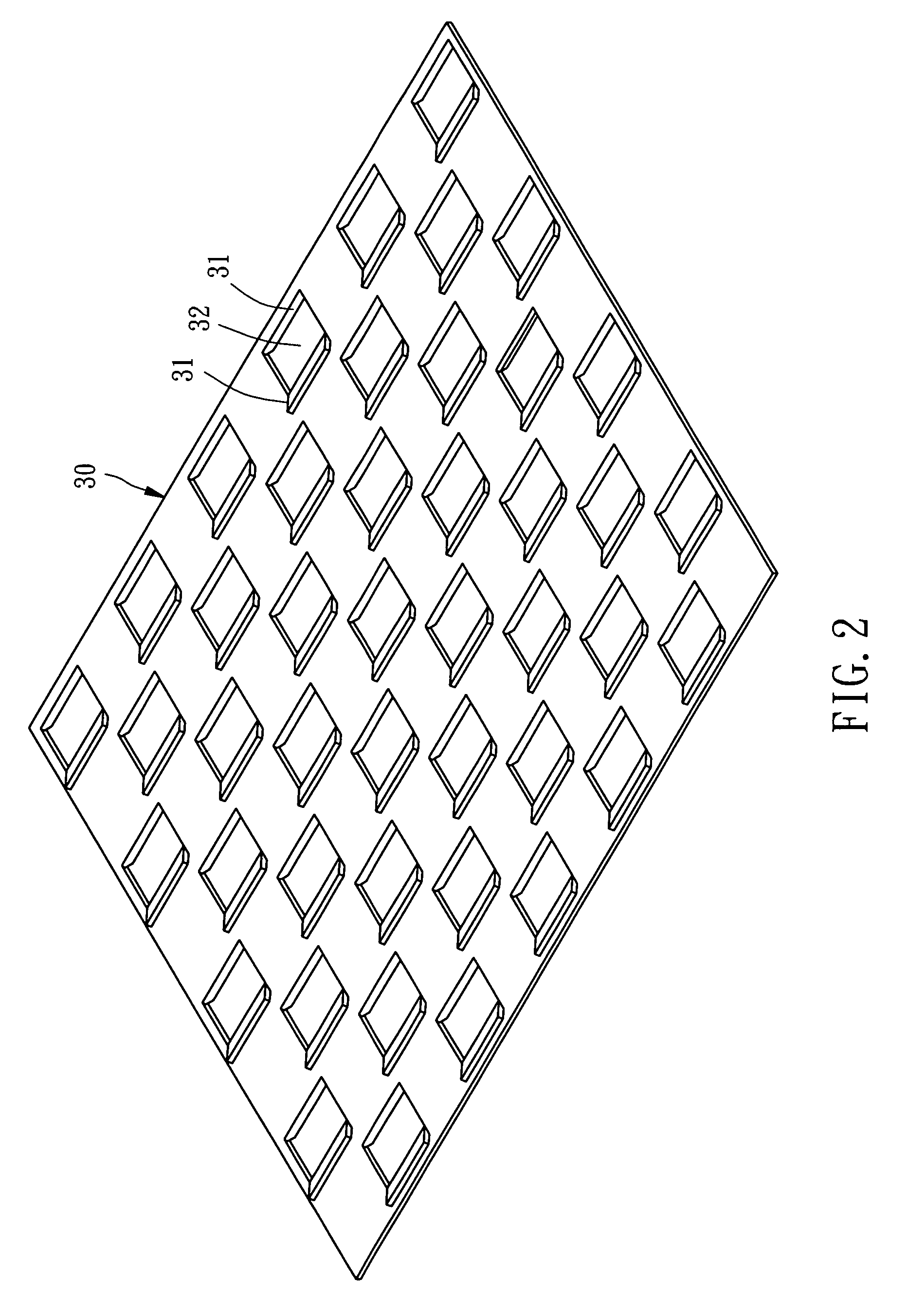
[0014]Referring to FIG. 1, a quick temperature-equalizing heat-dissipating device 100 for dissipating the heat while an electronic component 200 is running, constructed according to a preferred embodiment of the present invention, is composed of a hermetic container 10, two metallic nets 20, a metallic sheet 30, and a liquid working medium 40.

[0015]The hermetic container 10 includes a shell 11 and a cover 12 welded with the shell 11, having a vaporization end 10a and a condensation end 10b. The vaporization end 10a has an external side, to which the electronic component 200 is mounted, and an internal side, which is an internal bottom side 101 of the hermetic container 10. The condensation end 10b has an external side, at which a heat sink 50 is located, and an internal side, which is an internal top side 102 of the hermetic container 10. The heat sink 50 can be either mounted to or formed integrally on the condensation end 10b. The liquid working medium 40 is contained inside the h...


PUM


Abstract

A quick temperature-equalizing heat-dissipating device includes a hermetic container, a metallic sheet, and two metallic nets. The hermetic container contains a liquid working medium and has an internal top side and an internal bottom side. The metallic sheet is mounted inside the hermetic container, having a plurality of pores running therethrough and a plurality of support pieces protruding outward from its upper and lower surfaces respectively. The two metallic nets are supported by the support pieces to contact against the internal top and bottom sides of the hermetic container. Accordingly, the heat-dissipating device is based on the aforesaid heat-dissipating structure and the principle of working medium liquid phase transition to quickly equally dissipate the high heat flow density of an electronic component.

Description

BACKGROUND OF THE INVENTION[0001]1. Field of the Invention[0002]The present invention relates generally to heat-dissipating devices, and more particularly, to a quick temperature-equalizing heat-dissipating device.[0003]2. Description of the Related Art[0004]As the microelectronic technology develops rapidly, the size of linewidth of an IC chip is dramatically reduced and the IC tends to high density and high power. As the master frequency of the chip is increased, high heat flow density is produced and has become the principal bar against the technological development of the high-integration chip. More advanced chip indicates that there are more transistors on the integrated circuit, such that high heat and high power generated will result in high working temperature to reveal the faults resulted from various tiny physical flaws, like bridge fault. Further, the high working temperature will enlarge the interconnect resistance and increase the line delay, such that the delay fault s...

Claims


Application Information

Patent Timeline
IPC IPC(8): F28D15/00
CPCF28D15/025F28D15/04H01L23/427H01L2924/0002H01L2924/00
Inventor CHIN, CHI-TE
Owner CHIN CHI TE
Why Eureka
Try Eureka