Hydraulic vibration damper piston with an integral electrically operated adjustment valve

a technology of vibration damper and hydraulic piston, which is applied in the field of hydraulic vibration damper piston with an integral electrically operated adjustment valve, can solve the problems of increasing the space required for that assembly, limiting the rate of piston movement to dampen vibration,

Inactive Publication Date: 2009-11-26
HUSCO AUTOMOTIVE HLDG
View PDF14 Cites 67 Cited by
  • Summary
  • Abstract
  • Description
  • Claims
  • Application Information

AI Technical Summary

Benefits of technology

[0012]A control orifice is provided through which fluid can flow continuously between the first chamber and the pilot chamber, and a variable orifice is provided through which fluid flows between the second chamber and the pilot chamber. An actuator, such as an electrical solenoid for example, is operably connected to vary the variable orifice in response to a control signal.
[0013]In one embodiment of the novel piston, the control orifice has a fixed size, and a fixed pilot orifice provides another flow path between the second chamber and the pilot chamber that is in parallel with the variable...

Problems solved by technology

The orifices restricted the rate of that fluid flow, thereby limiting the rate of piston movement to dampen the vibration.
The ...

Method used


Image

  • Hydraulic vibration damper piston with an integral electrically operated adjustment valve
  • Hydraulic vibration damper piston with an integral electrically operated adjustment valve
  • Hydraulic vibration damper piston with an integral electrically operated adjustment valve

Examples


Embodiment Construction

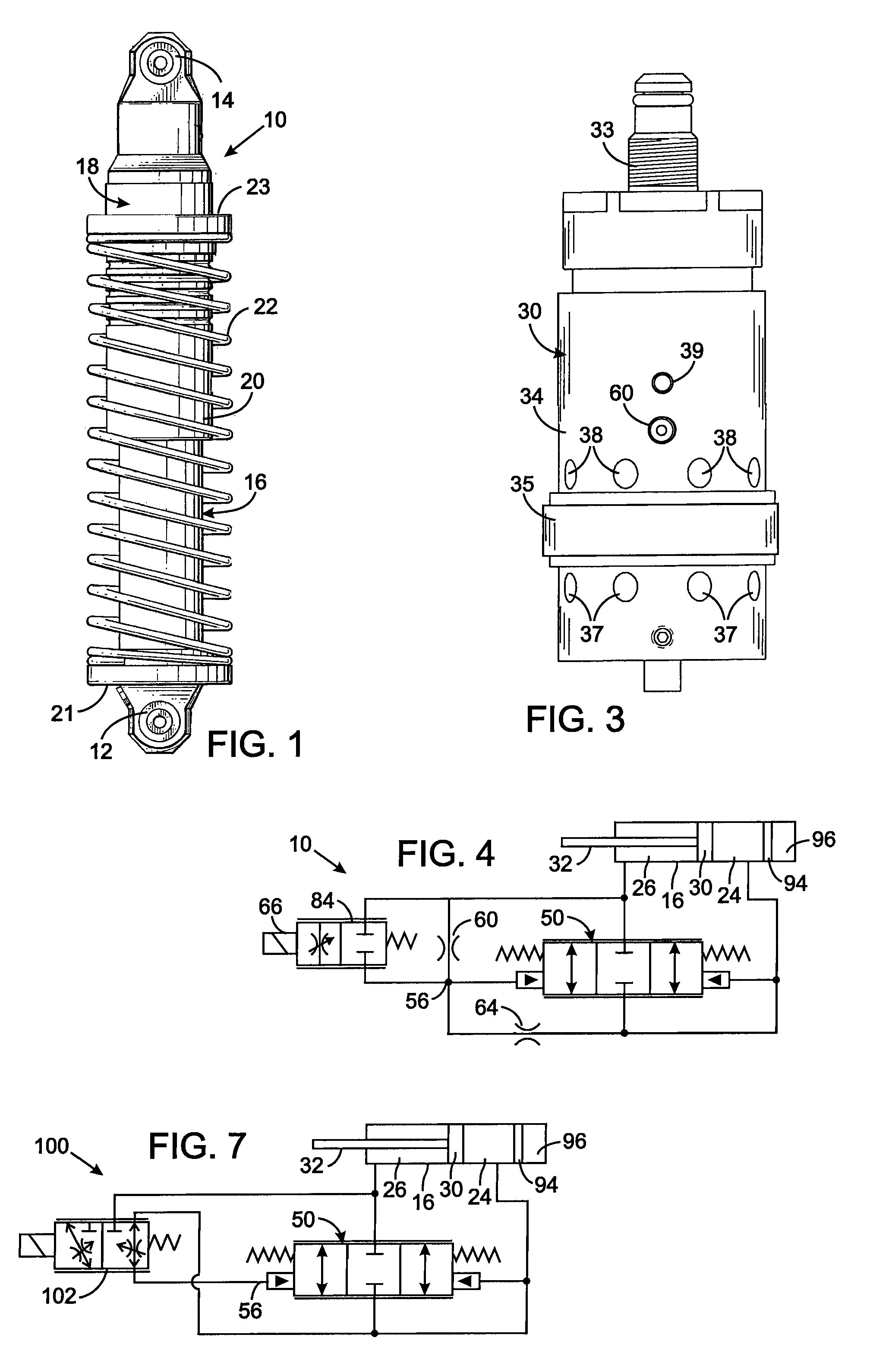
[0022]With initial reference to FIG. 1, a mono-tube vibration damper 10 has first and second couplings 12 and 14, which enable the device to be attached between two components of a vehicle to reduce transmission of vibrations from one component to the other. The first coupling 12 is at an end of a cylinder 16 and typically is attached to the wheel suspension of the vehicle. The second coupling 14 at one end of a piston assembly 18 typically is attached to the body of the vehicle. The piston assembly 18 has a tubular skirt 20 extending around the cylinder 16 in a manner that allows the piston assembly and the cylinder to move longitudinally with respect to each other. The particular vibration damper 10 has an external spring 22 between a flange 21 on the cylinder 16 and another flange 23 on the piston assembly 18. However, the present invention can be employed with vibration dampers that do not have an external spring. Motion of the two vehicle components attached to couplings 12 and...


PUM


Abstract

A vibration damper piston includes a piston body with a bore from which first and second apertures respectively provide paths to first and second chambers of the vibration damper. A valve spool in the bore defines a pilot chamber and controls fluid flow between the first and second apertures. First and second springs bias the valve spool in opposing directions. A control orifice provides a continuous fluid path between the first chamber and the pilot chamber, and a variable orifice provides another fluid path between the second chamber and the pilot chamber. An actuator is operably connected to adjust the variable orifice in response to a control signal.

Description

CROSS-REFERENCE TO RELATED APPLICATIONS[0001]Not applicableSTATEMENT REGARDING FEDERALLY SPONSORED RESEARCH OR DEVELOPMENT[0002]Not ApplicableBACKGROUND OF THE INVENTION[0003]1. Field of the Invention[0004]The present invention relates to apparatus, such as shock absorbers, for damping vibration in a motor vehicle, and more particularly to such apparatus having a dynamically adjustable damping characteristic.[0005]2. Description of the Related Art[0006]Hydraulic shock absorbers are commonly placed between the axles and the frame of a motor vehicle to reduce transmission of vibration from the wheels. Large trucks and off-road vehicles used in construction and agriculture incorporate similar vibration damping devices between the vehicle frame and the operator cab or between a seat and the vehicle body. The purpose of all these apparatus is to isolate the occupants from vibrations produced as the vehicle travels over the ground.[0007]A typical prior hydraulic vibration damper comprised...

Claims


Application Information

Patent Timeline
IPC IPC(8): F16F9/34F16F9/50F16J1/00
CPCF16F9/466
Inventor MURRAY, TODD MICHAELVAN WEELDEN, CURTIS L.HAMKINS, ERIC PETER
Owner HUSCO AUTOMOTIVE HLDG
Why Eureka
Try Eureka