Switching power supply and portable device

Active Publication Date: 2009-11-26
ROHM CO LTD
View PDF5 Cites 40 Cited by
  • Summary
  • Abstract
  • Description
  • Claims
  • Application Information

AI Technical Summary

Benefits of technology

[0019]According to the present invention, the switching power supply and the portable device, which achieve a high-efficiency in a full load area, can be provided.
[0020]According to the switching power supply of a present invention, since the efficiency at the time of no-load required with a cellular phone etc. is substantially improvable, the extension of a stand by time period can be achieved.
[0021]

Problems solved by technology

Accordingly, the efficiency of switching power supply was reducing

Method used


Image

  • Switching power supply and portable device
  • Switching power supply and portable device
  • Switching power supply and portable device

Examples


first embodiment

(Circuit Configuration)

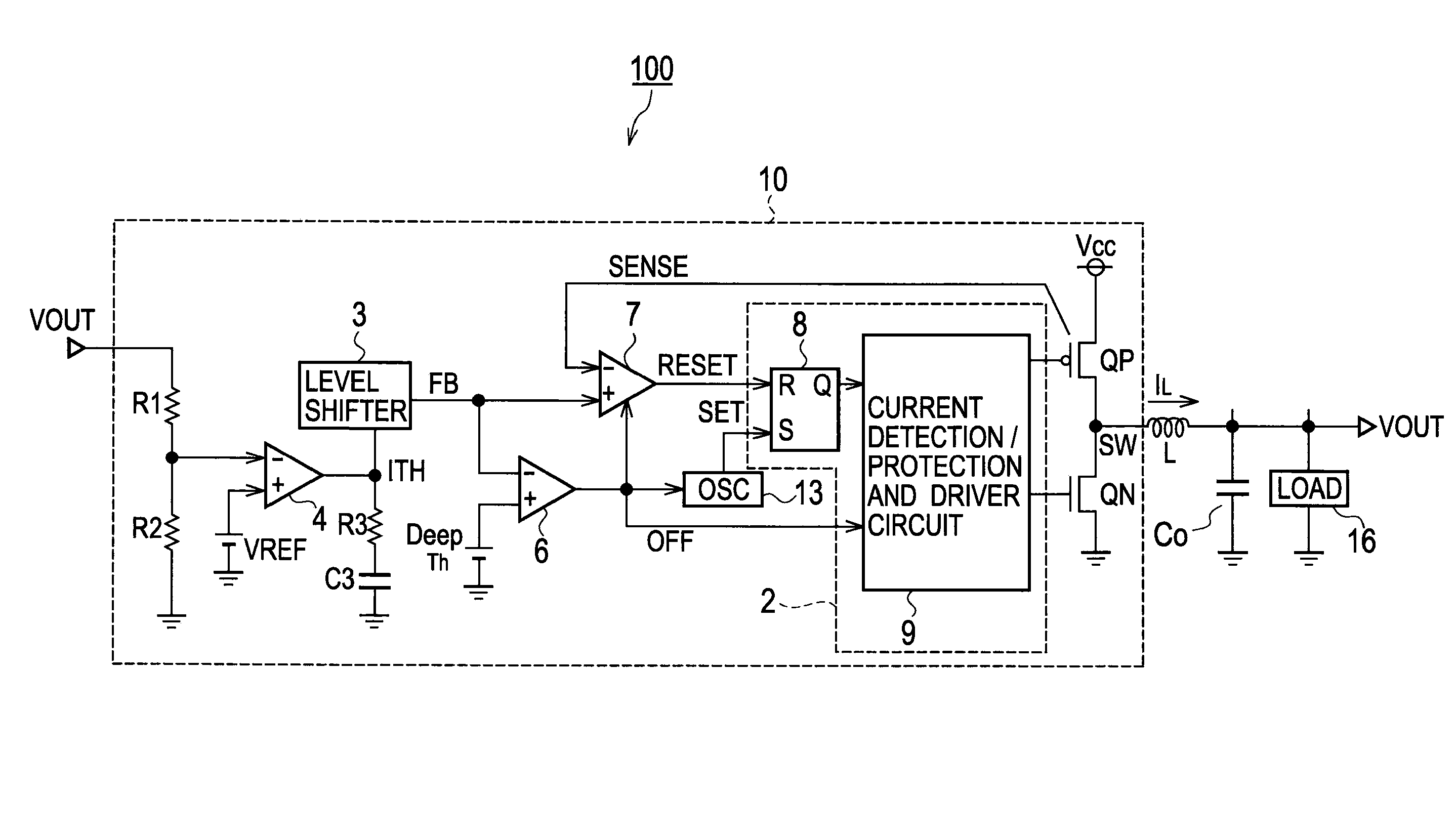
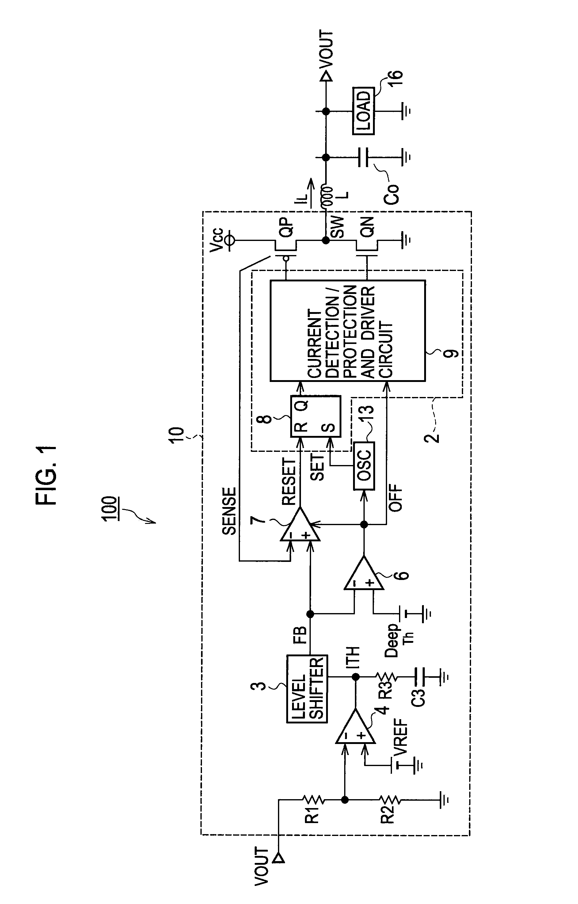
[0077]As shown in FIG. 1, a configuration of the switching power supply 100 according to a first embodiment of the present invention includes a switching regulator 10 of a single channel, a coil L connected to the switching terminal SW, and a capacitor Co and a load 16 connected to the coil L. As the load 16 connected to the switching regulator 10, mobile computing devices, such as a cellular phone, a smart phone, PDA, a portable media player, a digital camera, and wireless LAN, etc. are applicable, for example.

[0078]A power supply voltage Vcc is an input power voltage, and PWM current mode PWM and an output voltage VOUT by which DSLLM control is performed are obtained from the both terminals of the load 16.

[0079]As shown in FIG. 1, a schematic circuit configuration of the switching power supply 100 according to the first embodiment of the present invention includes: switching elements (QP, QN) which are connected to the power supply voltage Vcc and perform ON...

second embodiment

[0141]The switching power supply 120 according to a second embodiment of the present invention is provided with the two-channel configuration which arranges switching regulators 10a and 10b of a single channel to two-piece parallel, as shown in FIG. 9.

[0142]Although each switching terminal SW1 of the switching regulators 10a and 10b and SW2 are independently provided with a coil and a capacitor and a load which are connected to the coil, respectively, as well as the first embodiment, the illustration is omitted about these coil, capacitor, and load. As the load 16, mobile computing devices, such as a cellular phone, a smart phone, PDA, a portable media player, a digital camera, and wireless LAN, etc. are connectable as well as the first embodiment, for example.

[0143]The switching power supply 120 according to the second embodiment arranges the switching regulators 10a and 10b with a two-channel configuration, and operates on the frequency in synchronization with the first signal CLK...


PUM


Abstract

A switching power supply includes a switching element connected to a power supply voltage and performs ON and OFF operation; a control circuit; a coil; a capacitor connected to the coil and performs a rectifying operation with the coil; an oscillator to output an oscillator signal to the control circuit; a first comparator for comparing a current detection voltage which transforms a detection current flowing through the coil into a voltage, and the feedback voltage according to a difference of a voltage according to an output voltage with a reference voltage; and a second comparator for comparing a deep threshold voltage set as a value higher than the current detection voltage and is lower than the power supply voltage, with the feedback voltage. A Deep Simple Light Load Mode control is introduced to improve efficiency in a light or no-load area in addition to PWM mode in a heavy loading.

Description

CROSS REFERENCE TO RELATED APPLICATIONS AND INCORPORATION BY REFERENCE[0001]This application is based upon and claims the benefit of priority from prior Japanese Patent Applications No. P2008-135964 filed on May 23, 2008, the entire contents of which are incorporated herein by reference.TECHNICAL FIELD[0002]The present invention relates to a switching power supply which reduces the loss at the time of light load, and improves efficiency. In particular, the present invention relates a switching power supply for adopting the current mode switching for detecting a coil current of an output side coil and performing switching control, and a portable device which mounts the aforementioned switching power supply and reduces the power consumption.BACKGROUND ART[0003]In an operation of switching power supply, the power consumption loss by circuit current becomes large relatively rather than the loss over load current, in a state with a low amount value of load current. Accordingly, the effic...

Claims


Application Information

Patent Timeline
IPC IPC(8): G05F1/10
CPCH02M3/156Y02B70/16H02M2001/0032Y02B70/10H02M1/0032
Inventor HOJO, YOSHIYUKINAKABAYASHI, HIROTAKA
Owner ROHM CO LTD
Why Eureka
Try Eureka