Transformer apparatus with shielding architecture and shielding method thereof

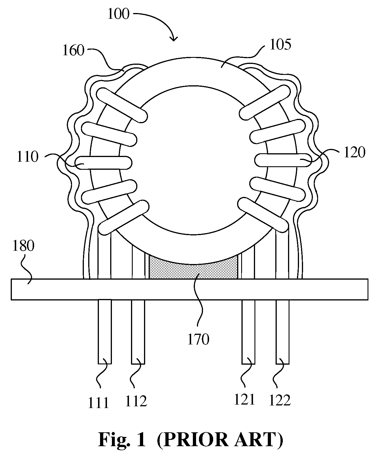
a transformer and shielding technology, applied in the direction of transformer/react mounting/support/suspension, magnetic body, printed circuit non-printed electric components association, etc., can solve the problems of noise generation device, power line disturbance, transformer apparatus b>100/b> cannot offer protection against external electrical noise, etc., to achieve the effect of protecting against erosion

Inactive Publication Date: 2009-11-26
SERCOMM
View PDF22 Cites 25 Cited by
  • Summary
  • Abstract
  • Description
  • Claims
  • Application Information

AI Technical Summary

Benefits of technology

[0009]In accordance with an objective of the present invention, a transformer apparatus having functionalities of shielding external electronic noises and protecting against erosion is provided. The transformer apparatus comprises a toroidal core, a primary winding, a secondary winding, a protection tape, a metal foil, and an UL tube. The primary winding is wound around the toroidal core at one side. The secondary winding is wound around the toroidal core at the other side opposite to the primary winding. The protection tape is wrapped around the primary winding and the secondary winding. The metal foil encloses the protection tape. The UL tube enfolds the metal foil.

Problems solved by technology

However, the conventional transformer apparatus 100 is not able to offer protection against external electrical noises, and it is well known that there are noise-generating devices everywhere, which function as noise sources to other peripheral electronic devices.
The electrical noises from such noise-generating devices may cause a power line disturbance due to a fluctuating magnetic field in the toroidal core 105 affected by the noise-related electromagnetic interference and have a bad effect on other peripheral electronic devices.
Therefore, the electronic devices having voltage sensitive feature may be subject to a software malfunction or a hardware breakdown resulting from the external electrical noises.

Method used


Image

  • Transformer apparatus with shielding architecture and shielding method thereof
  • Transformer apparatus with shielding architecture and shielding method thereof
  • Transformer apparatus with shielding architecture and shielding method thereof

Examples


Embodiment Construction

[0020]Hereinafter, preferred embodiments of the present invention will be described in detail with reference to the accompanying drawings. Here, it is to be noted that the present invention is not limited thereto.

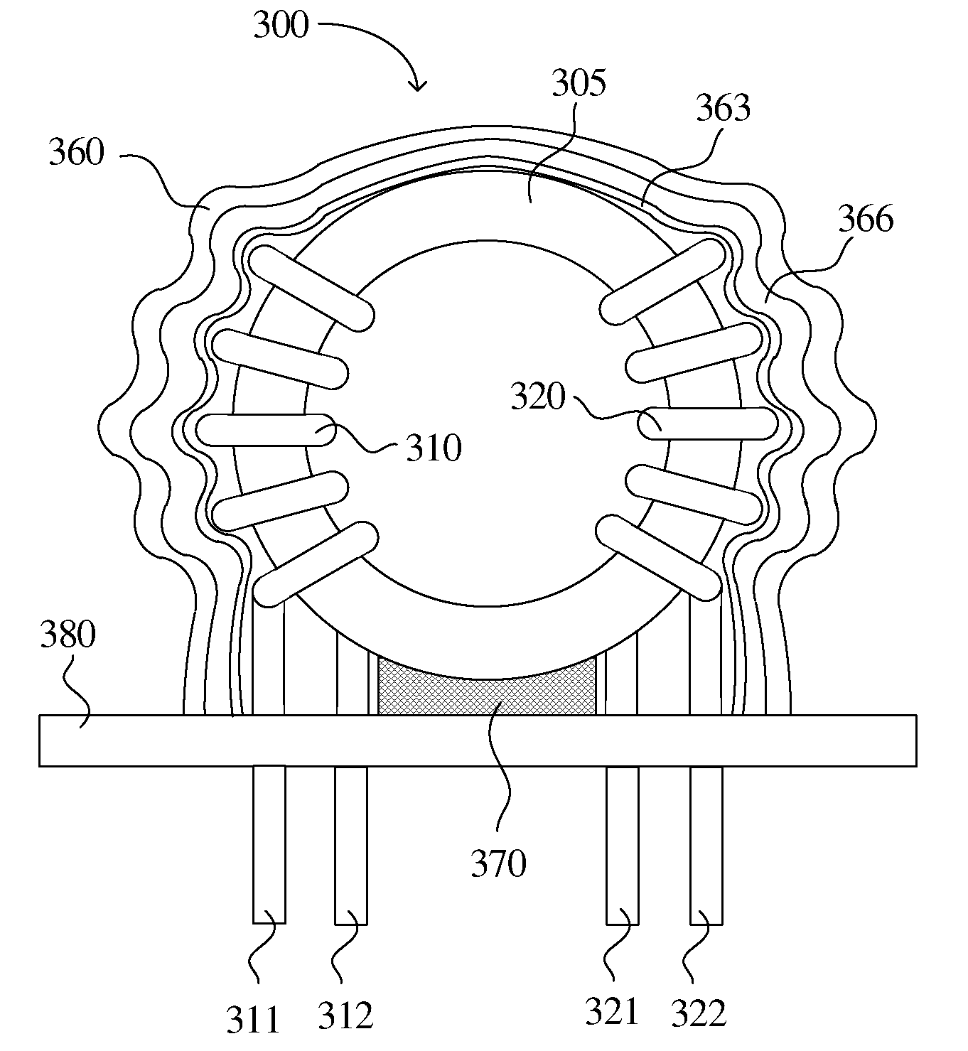
[0021]Please refer to FIG. 3 and FIG. 4. FIG. 3 is a schematic side view showing the configuration of a transformer apparatus in accordance with a first preferred embodiment of the present invention. FIG. 4 is a circuit diagram of the transformer apparatus shown in FIG. 3. The transformer apparatus 300 comprises a toroidal core 305, a primary winding 310, a secondary winding 320, a protection tape 363, a metal foil 366, an UL tube 360, an epoxy resin 370, a base 380, and a plurality of lead terminals 311, 312, 321 and 322. The epoxy resin 370 is utilized for mounting the toroidal core 305 onto the base 380.

[0022]The primary winding 310 having a predetermined number of turns is wound around the toroidal core 305 at one side. The primary winding 310 has two lead terminals 311...


PUM

PropertyMeasurementUnit
water resistantaaaaaaaaaa
magnetic fieldaaaaaaaaaa
voltage sensitiveaaaaaaaaaa

Abstract

A transformer apparatus and a transformer shielding method are provided for shielding external electronic noises and protecting against erosion. The transformer apparatus comprises a toroidal core, a primary winding, a secondary winding, a protection tape, a metal foil, and an UL tube. The primary winding and the secondary winding are wound around the toroidal core at opposite side to each other. The protection tape is wrapped around the primary winding and the secondary winding. The metal foil encloses the protection tape. The UL tube enfolds the metal foil. The transformer shielding method comprises wrapping a primary winding and a secondary winding of the transformer apparatus by a protection tape, enclosing the protection tape by a metal foil, and enfolding the metal foil by an UL tube.

Description

BACKGROUND OF THE INVENTION[0001]1. Field of the Invention[0002]The present invention relates in general to a transformer apparatus and a shielding method and, more particularly, to a transformer apparatus with shielding architecture and related shielding method.[0003]2. Description of the Prior Art[0004]Please refer to FIG. 1 and FIG. 2. FIG. 1 is a schematic side view showing the configuration of a conventional transformer apparatus. FIG. 2 is a circuit diagram of the transformer apparatus shown in FIG. 1. The conventional transformer apparatus 100 comprises a toroidal core 105, a primary winding 110, a secondary winding 120, an UL tube 160, an epoxy resin 170, a base 180, and a plurality of lead terminals 111, 112, 121 and 122.[0005]The primary winding 110 having a predetermined number of turns is wound around the toroidal core 105. The primary winding 110 has two lead terminals 111 and 112 to which an AC power source is applied. The secondary winding 120 having another predeterm...

Claims


Application Information

Patent Timeline
Patent Type & Authority Applications(United States)
IPC IPC(8): H01F27/36H01F27/28
CPCH01F27/022H01F27/2823H01F27/36H01F30/04H01F30/16H01F41/005Y10T29/4902H05K1/0218H05K1/18H05K3/284H05K2201/1003H05K2203/1311H01F41/08H01F27/363
Inventor YU, YUAN YUANCHEN, LI CHUNG
Owner SERCOMM
Why Eureka
Try Eureka