Fuel cell

a fuel cell and cell technology, applied in the field of fuel cells, can solve the problems of affecting the accuracy of fuel cell assembly, and the cracking of separation devices at locations, and achieve the effect of high accuracy and easy assembly

Inactive Publication Date: 2009-11-26
TOYOTA JIDOSHA KK
View PDF3 Cites 8 Cited by
  • Summary
  • Abstract
  • Description
  • Claims
  • Application Information

AI Technical Summary

Benefits of technology

[0011]In the fuel cell, the support members are located in areas with no through-holes on the outer peripheral portions of the separators. The fuel cell has seal members provided around the through-holes, through which a reactant gas flows, and the seal members also support separators between the separators. When the positions of the seal members are shifted when the separators are pressed from both sides, bending stress is exerted on the separators. In the fuel cell according to the first aspect of the present invention, the separators are less likely to be bent because the edges of the separators are supported by the support members. Therefore, in the case of metal separators, the separators do not bent until the edges of the separators come into contact with each other to cause an electrical short circuit. In the case of carbon separators, the separators may be prevented from developing cracks at locations where the seal members are misaligned relative to each other.
[0013]In the fuel cell according to the first aspect of the present invention, because the support members are formed integrally with the seal members, the number of parts can be reduced and the assembly of the fuel cell stack can be facilitated.
[0016]In the fuel cell according to the first aspect of the present invention, the pairs of separators, the seal members and the support members do not form an enclosed space. Therefore, the following effect is achieved. For example, when closed spaces are formed by the separators, support members, and seal members, the air in the closed spaces may expand because of self heating and flow beyond the seal members and support member to the side of the through-holes while the fuel cell is operating. Then, the sealability of the seal members formed around the through-holes deteriorates and the reactant gas flows through the through-holes and may leak to the outside. However, according to the fuel cell of the present invention, because a closed space is not formed, the force which causes gas to move beyond the seal members formed around the through-holes is not generated. Therefore, deterioration of sealability is prevented.
[0021]In the fuel cell according to the first aspect of the present invention, because the support members comprise an adhesive, each of the unit cells is integrated into a unitary body. Therefore, when a plurality of unit cells are stacked, the fuel cell stack may be easily assembled with high accuracy as compared to the case where the separators, electrodes, electrolyte membranes and so on are stacked individually.

Problems solved by technology

In the case of carbon separators, when the seal lines of the seal members S are misaligned relative to each other, the separators may develop cracks at locations where the seal members apply pressures.

Method used


Image

  • Fuel cell
  • Fuel cell
  • Fuel cell

Examples


first embodiment

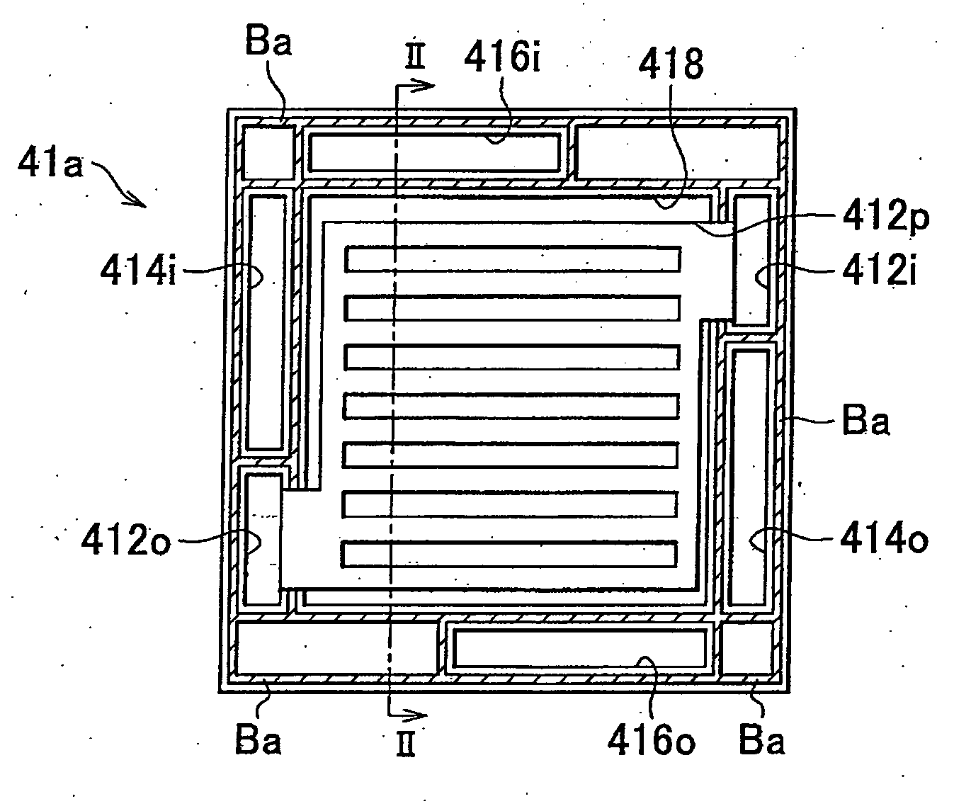
[0046]As in the case of the first embodiment, when a pressurizing load is applied to the anode side separator 41b and the cathode side separator 47b with an MEA 48 interposed therebetween so that the lower edge of the anode side separator 41b and the upper edge of the cathode side separator 47b are bonded to each other and the upper edge of the anode side separator 41b and the lower edge of the cathode side separator 47b are bonded to each other as shown in FIG. 4A and FIG. 4B and the adhesive Bb is cured, an integrated unit cell 40b is formed (FIG. 4C). Then, the adhesive Bb applied around the receiving parts 418 and 478 and around the through-holes functions as a seal member for preventing leakage of hydrogen, air, and coolant. The adhesive Bb applied linearly along the upper and lower edges of the separators 41b and 47b functions as a support member for supporting the fastening load described before on the edges of the separators. Because a pressurizing load is applied when the a...

second embodiment

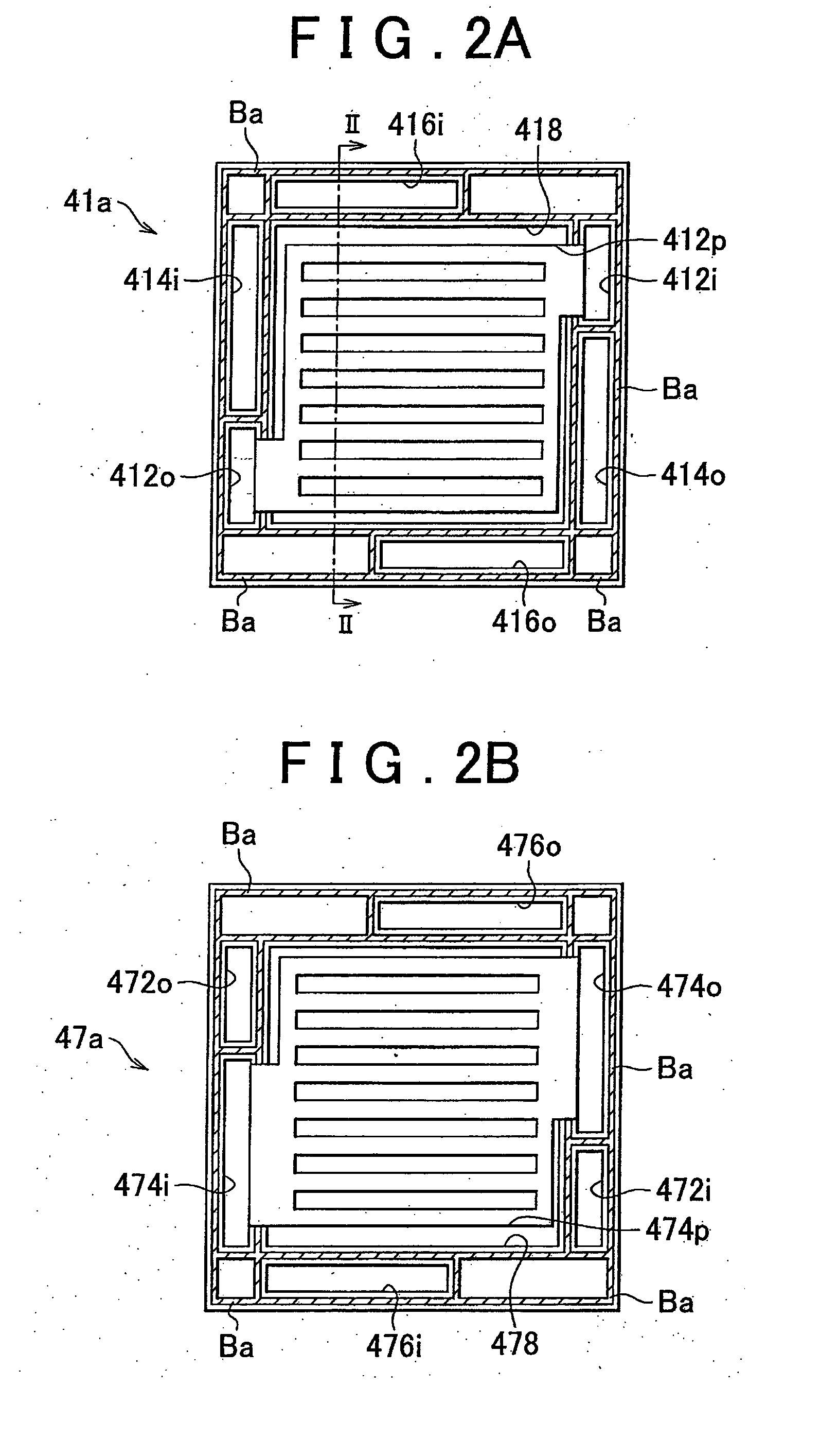
[0055]In addition, in the fuel cell stack of this embodiment, the adhesive Bc which functions as a seal member and the adhesive Bc which functions as a support member for supporting the fastening load exerted on the separators do not form any closed region. Thus, when the anode side separator 41c and the cathode side separator 47c are bonded to each other to form an integrated unit cell 40c, any closed space containing air is not formed in the unit cell 40c as in the Therefore, the adhesive Bc applied around the through-holes may be prevented from being broken and its function as a seal member is not impaired.

[0056]In addition, in the fuel cell stack of this embodiment, because the adhesive Bc is applied in spots on the anode side separator 41c and the cathode side separator 47c except for the areas around the receiving part 418 and around the through-holes, the amount of the adhesive Bc can be reduced. Therefore, the cost and weight of the fuel cell stack can be decreased.

[0057]D....


PUM

PropertyMeasurementUnit
areasaaaaaaaaaa
elasticityaaaaaaaaaa
heat resistanceaaaaaaaaaa

Abstract

On an anode side separator, an adhesive is applied linearly along the upper and lower edges of the four edges thereof, around a receiving part and around a through-hole and so on. On a cathode side separator, the adhesive is applied at the same locations as on the anode side separator. The adhesive functions as support members for supporting the fastening load on the edges of the separators.

Description

BACKGROUND OF THE INVENTION[0001]1. Field of the Invention[0002]The present invention relates to a fuel cell, and more particularly, to a fuel cell having a stack structure in which a plurality of unit cells are stacked on top of one another.[0003]2. Description of the Related Art[0004]A fuel cell stack has a stack of unit cells each having an electrolyte membrane, a pair of electrodes disposed on both sides of the electrolyte membrane, and a pair of separators disposed outside the electrodes. In such a fuel cell stack, a fuel gas is supplied to the anode of each unit cell through a fuel gas supply manifold. Similarly, an oxidant gas is supplied to the cathode of each unit cell through an oxidant gas supply manifold. The manifolds extend in the stacking direction through the fuel cell stack. Each separator has an outer peripheral portion through which through-holes are formed, and the through-holes define the manifolds when the unit cells are stacked on top of one another. In such a...

Claims


Application Information

Patent Timeline
Patent Type & Authority Applications(United States)
IPC IPC(8): H01M8/10
CPCH01M8/0228H01M8/0247H01M8/0276Y02E60/50H01M8/248H01M2008/1095H01M8/0284H01M8/0273H01M8/241H01M8/2483H01M8/0267H01M8/0297
Inventor TANAKA, TAKUMIFUJITA, TSUGUHIRO
Owner TOYOTA JIDOSHA KK
Why Eureka
Try Eureka