Radio-frequency communication device, system and method

a radio frequency communication and communication device technology, applied in the field of radio frequency contactless communication, can solve problems such as the problem of integrating such a function in a mobile devi

Inactive Publication Date: 2009-11-26
COMMISSARIAT A LENERGIE ATOMIQUE ET AUX ENERGIES ALTERNATIVES
View PDF3 Cites 30 Cited by
  • Summary
  • Abstract
  • Description
  • Claims
  • Application Information

AI Technical Summary

Benefits of technology

[0032]In other words, the device according to the invention is capable of generating a signal when there is no signal on the antenna terminals, as may be the case, for instance, if the reader is a type A read

Problems solved by technology

The power required therefore makes integrating

Method used


Image

  • Radio-frequency communication device, system and method
  • Radio-frequency communication device, system and method
  • Radio-frequency communication device, system and method

Examples


first embodiment

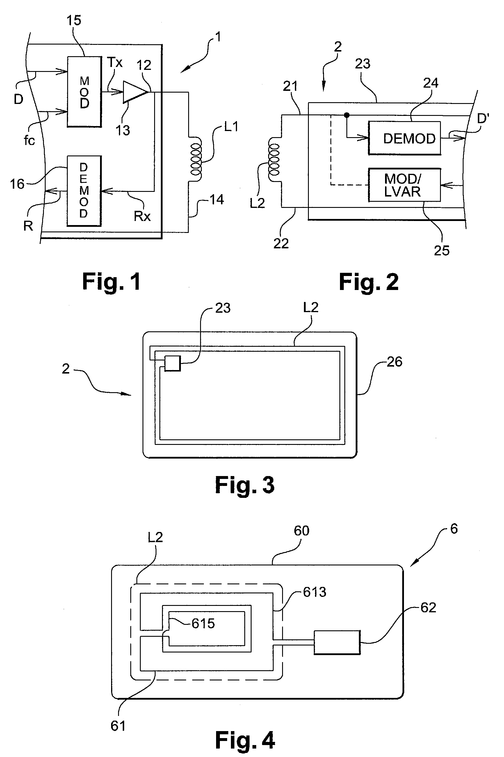
[0059]FIG. 4 is a highly schematic top view of a device 60 according to the invention, for example a contactless reader fitted in a mobile phone or a digital personal assistant.

[0060]Device 60 formed, for example, on a printed circuit wafer, comprises an antenna 61 consisting of a single conductor shaped as first loop 613 and second loop 615 nested inside first loop 613 with loops 613 and 615 having opposite flow directions.

[0061]Device 60 also comprises an integrated circuit 62 connected to the terminals of antenna 61 which is in charge of transmission and reception of data by antenna 61 as explained below in greater detail.

[0062]The surface areas of loops 613 and 615 are preferably substantially equal so that, when antenna 61 is exposed to a homogeneous magnetic field, the electromotive forces induced in loops 613 and 615 cancel each other out. The sensitivity of antenna 61 to a homogeneous magnetic field is thus minimized.

[0063]Also, the dimensions of antenna 61 are preferably ch...

second embodiment

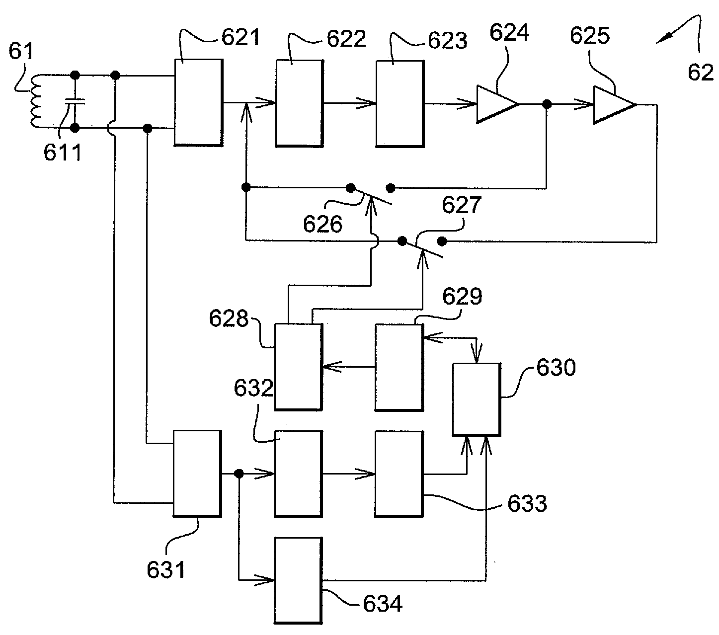
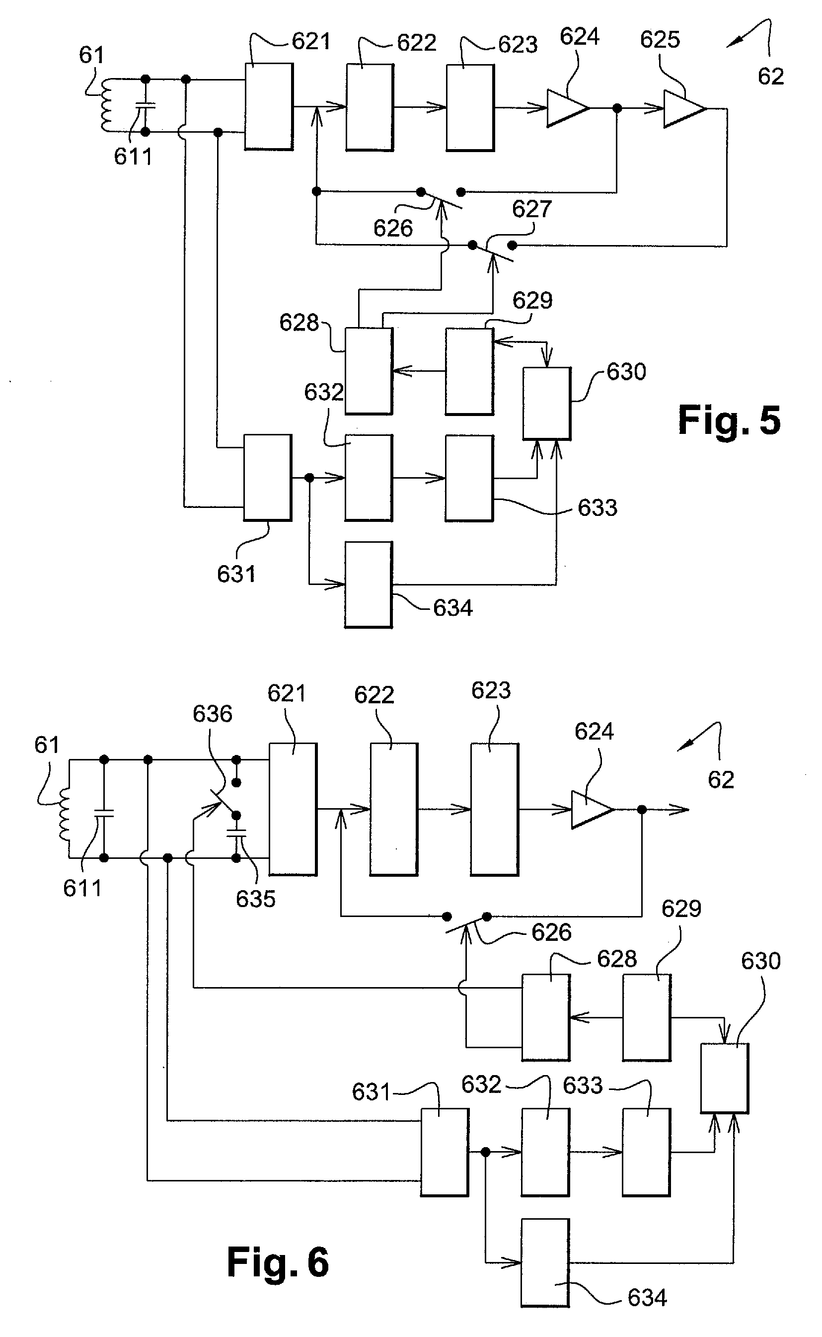
[0078]FIG. 6 schematically shows circuit 62 which is especially suitable if the contactless reader is type B and the contactless card is type A.

[0079]In order to interrogate the contactless card, the second embodiment differs from that described in relation to FIG. 5 in that, instead of second multiplier 625 and associated second switch 627, a second capacitor 635 is connected to the terminals of antenna 61 via switch 636 in order to vary the antenna tuning, thereby producing type A carrier amplitude modulation.

[0080]The output signal of multiplier 624 therefore provides a high-level reference signal which is modulated by means of the second capacitor 635 and controllable switches 626, 636.

third embodiment

[0081]FIG. 7 schematically shows circuit 62 which is especially suitable if the contactless reader is type A, regardless of contactless-card type.

[0082]In this third embodiment, in order to interrogate the contactless card, circuit 62 comprises an oscillator 637 which generates a sine-wave signal having a frequency substantially equal to that of the carrier of the fixed reader and synchronized with the carrier, for example by means of a phase-locked loop (not shown).

[0083]A first variable-gain multiplier 638 and a second multiplier 639 are connected in series to oscillator 637; the second multiplier 639 is connected via a first switch 640. The outputs of the first and second multipliers 638, 639 are also connected respectively to the non-inverting and inverting terminals of a first subtracter 641.

[0084]Adder 642 is connected, via its inverting terminal, to the output of the first subtracter 641. The output of second subtracter 642 is connected, via a second switch 643, by its non-in...


PUM


Abstract

The invention relates to a radio-frequency communication device comprising an inductive antenna in order to communicate with a transponder. According to the invention, the antenna is capable of establishing weak coupling with a transmitter which produces a magnetic field which is substantially homogeneous on the scale of the antenna and is also capable of establishing strong inductive coupling with a transponder located in the vicinity of the device, with the device comprising a transponder interrogation circuit comprising means of sampling and processing the signal on the antenna terminals which are capable of producing a reference signal as a function of said signal; modulation means capable of modulating the reference signal; and application means capable of applying the modulated signal to the antenna terminals.

Description

CROSS REFERENCE TO RELATED APPLICATIONS[0001]This application claims priority under 35 U.S.C. §119 from French Patent Application No. 08 53410 filed on May 26, 2008 in the French Patent Office, the entire disclosure of which is incorporated herein by reference.FIELD OF THE INVENTION[0002]The invention relates to the field of radio-frequency contactless communication and, more especially, radio-frequency communication by inductive coupling.BACKGROUND OF THE INVENTION[0003]A contactless communication device such as that defined by Standards ISO 14443, ISO 1593 or ISO 18000-X, for example, usually comprises an inductive antenna formed by an electrical conductor which forms one or more loops and is connected to an integrated circuit which causes the voltage and / or load across the terminals of the antenna to vary in order to generate an amplitude-modulated or phase-modulated magnetic field. Communication can thus be established with another device of this type located within the communic...

Claims


Application Information

Patent Timeline
IPC IPC(8): H04B5/00H01Q21/00H01Q7/00H04B1/38
CPCG06K7/0008G06K7/10207H04B5/0018H04B5/0087H04B5/0037H04B5/0056H04B5/0081H04B5/0031
Inventor SAVRY, OLIVIER
Owner COMMISSARIAT A LENERGIE ATOMIQUE ET AUX ENERGIES ALTERNATIVES
Why Eureka
Try Eureka