Method and device for recognizing tissue structure using doppler effect

a tissue structure and doppler effect technology, applied in the field of tissue structure recognition using doppler effect, can solve the problems of limited use, inability of treating physicians to use dedicated devices, wires, catheters, etc., and consequent absence of contrast materials, etc., to direct the invasive tool through the occlusion

Inactive Publication Date: 2009-11-26
MEDINOL LTD
View PDF18 Cites 18 Cited by
  • Summary
  • Abstract
  • Description
  • Claims
  • Application Information

AI Technical Summary

Benefits of technology

[0010]In particular, the apparatus and method of the invention provide an imaging tool for use with an imaging system that enables an operator to visualize an interventional device and a target organ. In broad terms, the imaging tool comprises a vibratory transducer and a vibratable element. When energized, the vibratory transducer is capable of generating at least one vibration frequency for causing a vibration motion in the vibratable element, and the vibratable element is thereby capable of oscillating a target or target organ (the terms target and target organ are used interchangeably herein) with an amplitude, in parti...

Problems solved by technology

Because adequate imaging requires injection of a contrast material into the vessel and adequate blood flow, however, its use is limited where blood flow is reduced or blocked.
For example, if an artery is totally occluded—as in the case of chronic total occlusions (“CTO”)—the consequent absence of contrast material does not permit visualization of the designated artery and plaque to be treated.
Therefore, the treating physician cannot use the technique to direct the invasive tool, wire, cathete...

Method used


Image

  • Method and device for recognizing tissue structure using doppler effect
  • Method and device for recognizing tissue structure using doppler effect
  • Method and device for recognizing tissue structure using doppler effect

Examples


Embodiment Construction

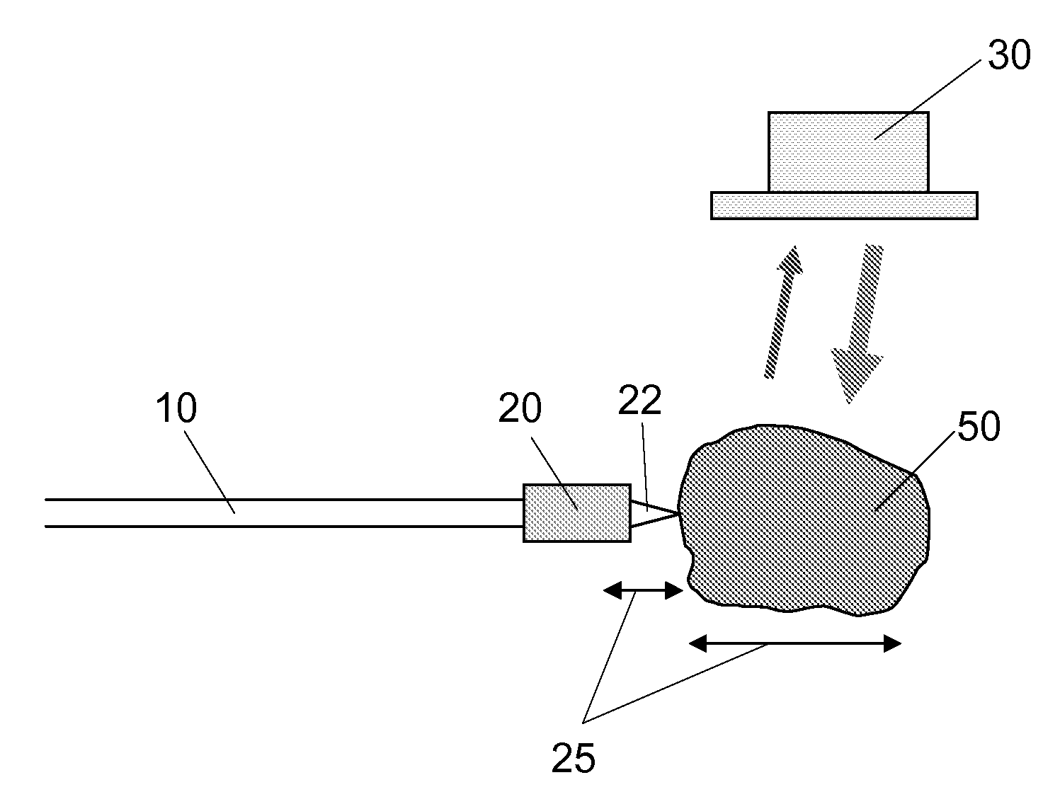
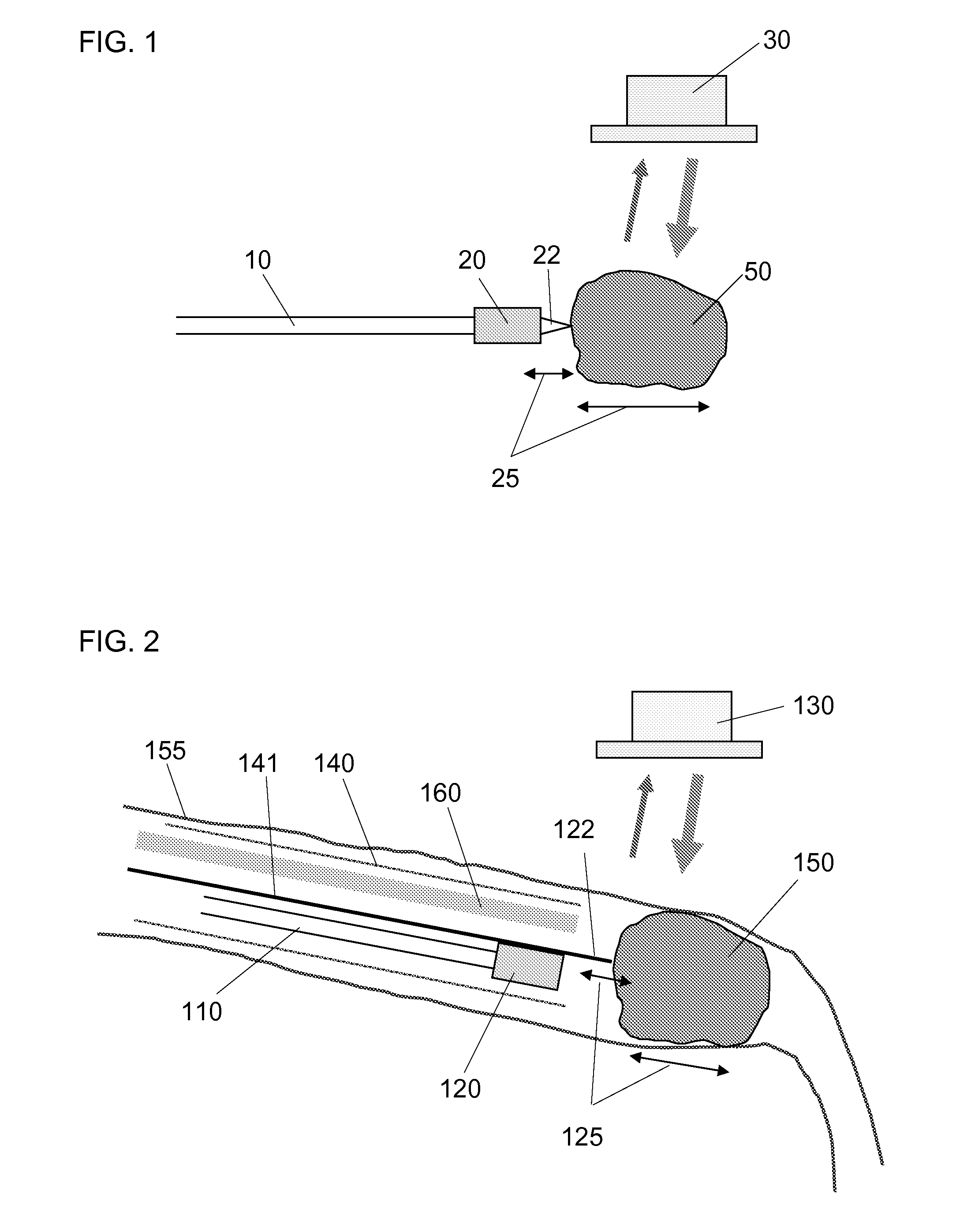
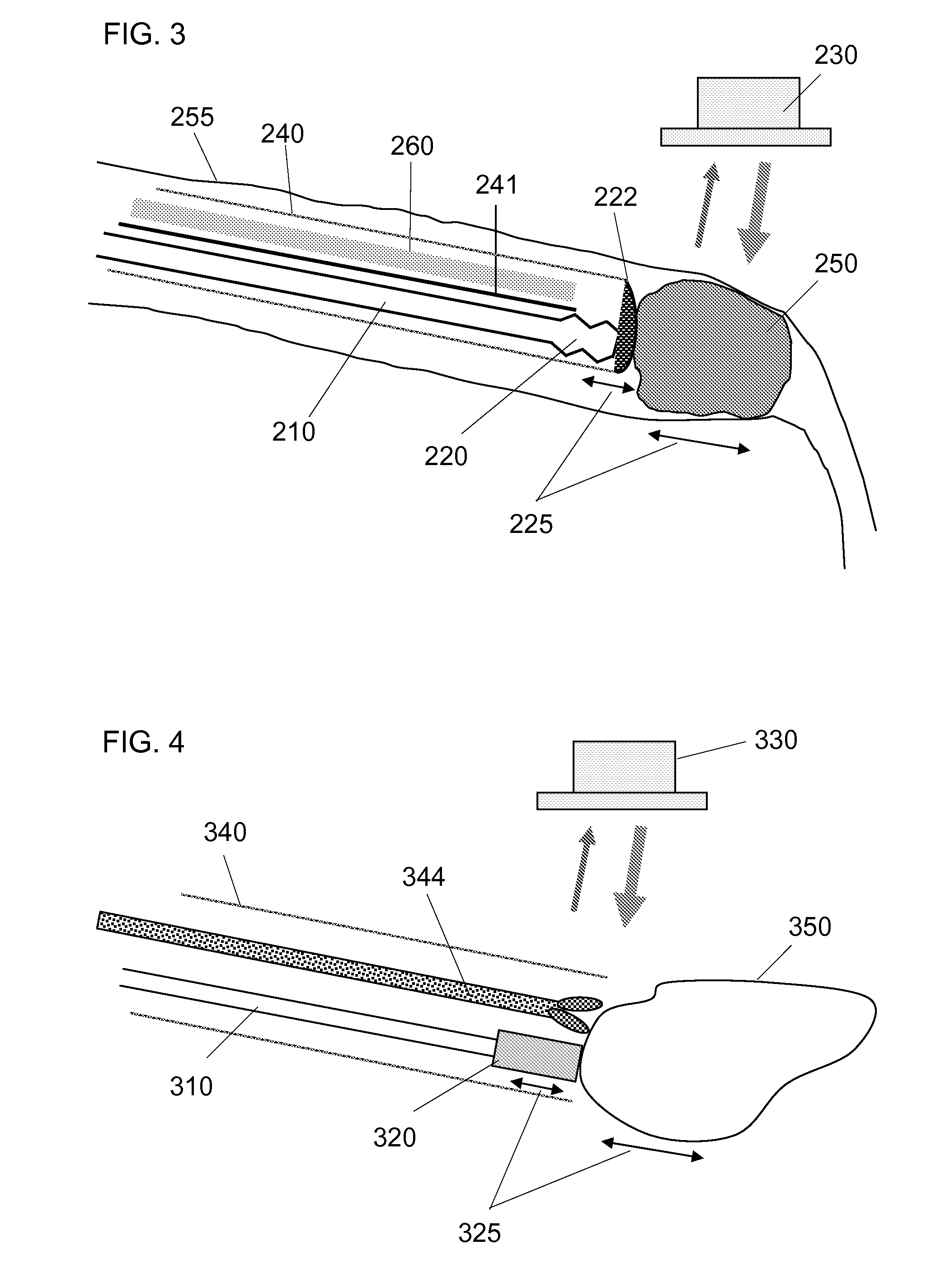
[0020]The present invention is directed to an apparatus, method and system for visualizing the distal end of an interventional device and the organ or lesion that is the target of the interventional device. The apparatus of the invention comprises an imaging tool for use with an ultrasound imaging apparatus. The imaging tool comprises a vibratory transducer and a vibratable element. The vibratory transducer is capable of generating vibrational energy to effect a vibration motion in the vibratable element at first imaging frequency of about 2 Hz to about 2 kHz (a low frequency), hereinafter also referred to as simply a first frequency. The vibratable element is capable of causing a target organ to oscillate at a second imaging frequency of about 2 Hz to about 2 kHz (a low frequency), with an amplitude of less than about 2 mm peak to peak (hereinafter referred to as a small amplitude), such that the operator can introduce the imaging tool into a body tissue or lumen in need of treatme...


PUM


Abstract

An apparatus, method and system comprising an imaging tool for imaging an interventional device and its target organ using Doppler ultrasound are disclosed. The apparatus comprises an imaging tool and an interventional medical device; in some embodiments the imaging tool itself may be an interventional device or may comprise components of the interventional device. The imaging tool comprises a vibratory transducer and a vibratable element. The vibratory transducer is energized to generate a vibration motion in the vibratable element at first imaging frequency, which in turn is capable of oscillating a target organ at a second imaging frequency, the imaging frequencies being detectable by an ultrasound imaging system with Doppler mode. In certain applications the vibratory transducer may be energized to vibrate at a therapeutic frequency to effect treatment of the target organ, for example to clear a lumenal or vascular stenosis or to penetrate a vascular occlusion.

Description

[0001]The present invention relates to ultrasonic imaging of interventional devices and target organs and, in particular, an imaging tool, comprising a vibratory transducer and a vibratable element, coupled to an ultrasonic imaging system that uses Doppler ultrasound. The vibratable element of the imaging tool is capable of rendering the interventional medical device and the target organ or internal tissue to be treated detectable to the imaging system thereby enhancing the visibility of each. The invention is particularly useful for interventional radiology and cardiology.BACKGROUND OF THE INVENTION[0002]In order to treat organs in a minimally invasive manner, physicians use various imaging methods, both for imaging the treated organs and to determine the absolute and relative position of the invasive tool with respect to the targeted organ. Some common methods, for example, are: X-ray fluoroscopy for imaging endovascular catheterization treatment; computed tomography (CT) or magne...

Claims


Application Information

Patent Timeline
IPC IPC(8): A61N7/00A61B8/00
CPCA61B5/0048A61B8/488A61B5/6851A61B5/0051
Inventor PANSKY, AMIR
Owner MEDINOL LTD
Why Eureka
Try Eureka