Electronic fishing device and a related system, method, and use

a fishing device and electronic technology, applied in the field of fishing equipment, can solve the problems of difficult handling of a downrigger, large control over the depth of the lure in water, and expensive equipment, and achieve the effects of slow and faster towing speed, simple use and manufacture, and small siz

a fishing device and electronic technology, applied in the field of fishing equipment, can solve the problems of difficult handling of a downrigger, large control over the depth of the lure in water, and expensive equipment, and achieve the effects of slow and faster towing speed, simple use and manufacture, and small siz

US20090293336A1Inactive Publication Date: 2009-12-03LIQUID ZONE

Image

  • Electronic fishing device and a related system, method, and use
  • Electronic fishing device and a related system, method, and use
  • Electronic fishing device and a related system, method, and use

Examples


Embodiment Construction

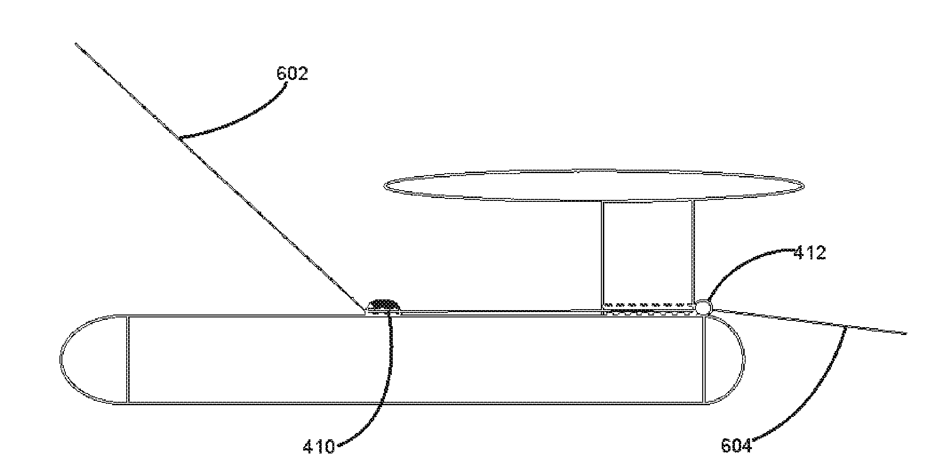
[0045]FIGS. 1-3 have already been reviewed in connection with introducing the background and summary of the invention. FIG. 4a illustrates a perspective view of one embodiment of an electronic fishing (aid) device in accordance with the present invention. The submersible device 402 comprises a control body 404, a hydrofoil 406 preferably assembled on the rear end of the control body 404, front fins 408 assembled in both of the front sides of the control body 404, a preferably adjustable towing / trolling point 410 with e.g. a hook, a ring, a projection, etc, on the front top of the control body 404, and a connection point, e.g. a hook or ring etc, for a lure 412 in the rear end of the control body 404. Although FIG. 4 provides one configuration, it should be understood that the device 402 may be in wide variety of sides, shapes and colors although the functionality of the equipment carried by the device 402 remains substantially the same.

[0046]The control body 404, best shown in Figur...


PUM


Abstract

An electronic fishing device for facilitating trolling a fish-catching element in water and a related system, method, and use, the fishing device including: a first sensing element for obtaining a first indication relating to water temperature, a second sensing element for obtaining a second indication relating to the depth of the device, a steering member for adjusting the depth of the device, a processing unit for controlling, via the first and / or second indication provided by the first and second sensing elements, the steering member so as to guide the device relative to at least one element selected from the group consisting of: the position of the thermocline layer, a predetermined depth, and a predetermined temperature. In addition to fishing the disclosed device may be utilized in marine or other underwater research.

Description

FIELD OF THE INVENTION [0001]This invention relates generally to fishing equipment. More particularly the present invention is directed to an electronic fishing device that may tow a lure or another element and apply information about water temperature and depth for device control purposes and optionally for determining the thermocline and seeking the right depth for desired species.BACKGROUND OF THE INVENTION [0002]Recreational and sport fishing has great global markets. Millions of anglers are counted throughout the world and their number is still growing. The invention described in this document relates closely to fishing with a lure or e.g. a baited hook trolled behind the boat. The number of trolling anglers in Europe, the USA and Canada is estimated to be over 40 millions. Typically, the anglers are fishing for a specific species and it is known that fish are active in varying temperatures species-specifically, as can be seen in FIG. 1, and also the richest area of various spe...

Claims


Application Information

Patent Timeline
03 Dec 2009
Publication
US20090293336A1
IPC
A01K97/00
CPC
A01K91/08; A01K97/00; A01K91/20; G05B1/01
Inventors
LANKINEN, PETTERI