Gas turbine combustor and method for supplying fuel to the same
a technology of gas turbine combustor and combustor body, which is applied in the direction of machines/engines, mechanical equipment, lighting and heating apparatus, etc., can solve the problem of insufficient reduction of discharged nox, and achieve the effect of reducing nox
- Summary
- Abstract
- Description
- Claims
- Application Information
AI Technical Summary
Benefits of technology
Problems solved by technology
Method used
Image
Examples
first embodiment
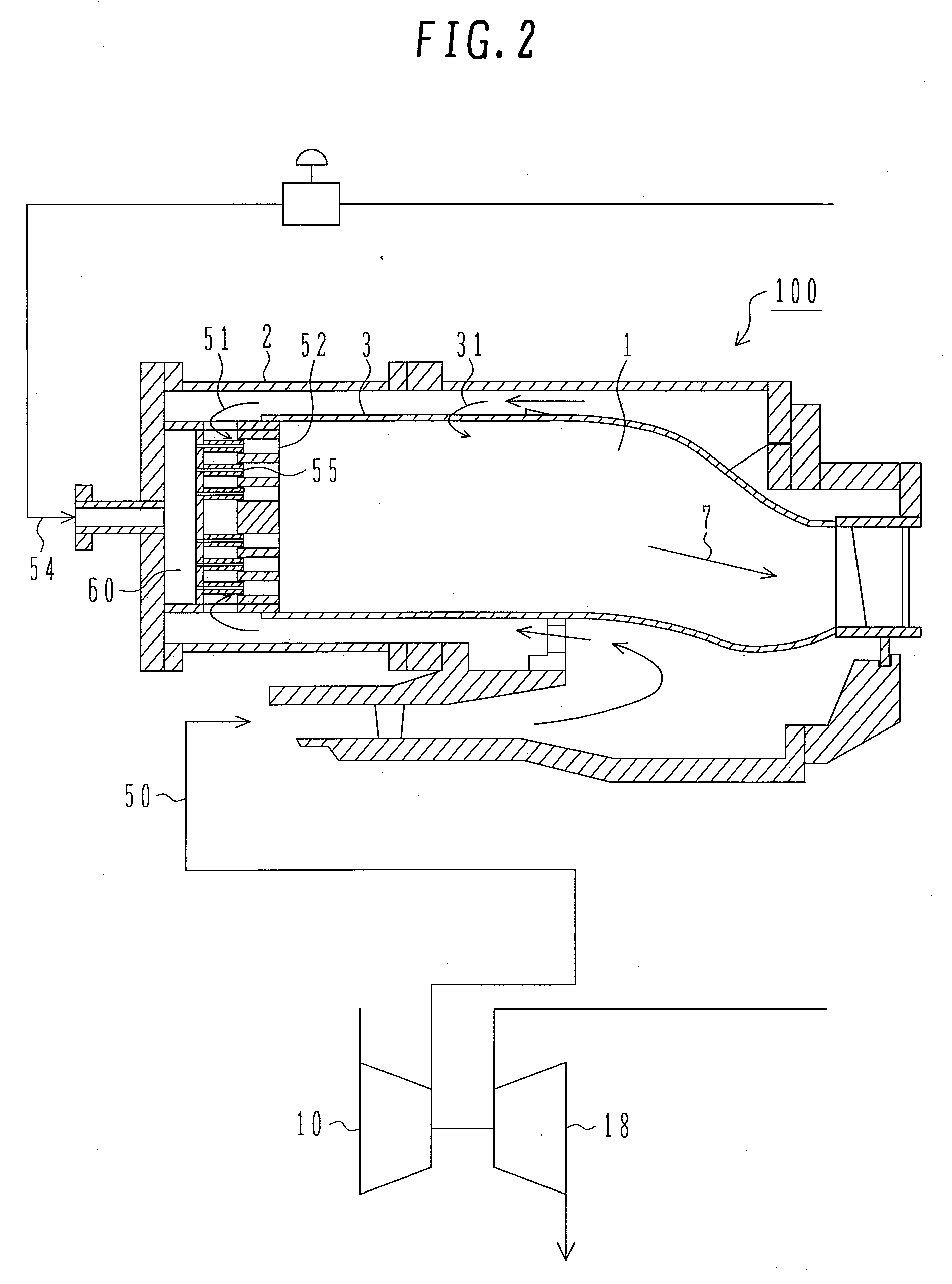
[0024]A first embodiment of the present invention will be described hereinunder with reference to the drawings. FIG. 2 is an entire sectional view of a gas turbine combustor according to this embodiment. In the same figure, the gas turbine of this embodiment is mainly composed of a compressor 10 for compressing air for combustion, a turbine 18 for driving a turbine shaft with use of combustion gas, and a combustor 100.
[0025]The compressor 10 compresses air supplied from the exterior and sends the thus-compressed air to the combustor.
[0026]Using high-temperature combustion gas produced from the combustor 100, the turbine 18 drives and rotates the turbine shaft to generate electric power.
[0027]The combustor 100 is mainly provided with a section for the supply of fuel and air, a combustor liner 3 and an outer cylinder 2. A fuel header 60 is installed inside the outer cylinder 2 of the combustor. The fuel header 60 feeds fuel 54 to a combustion chamber 1 defined within the combustor lin...
second embodiment
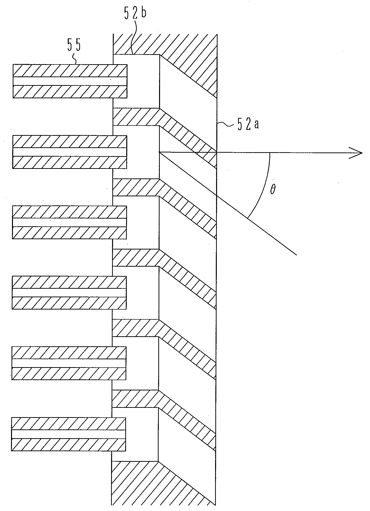
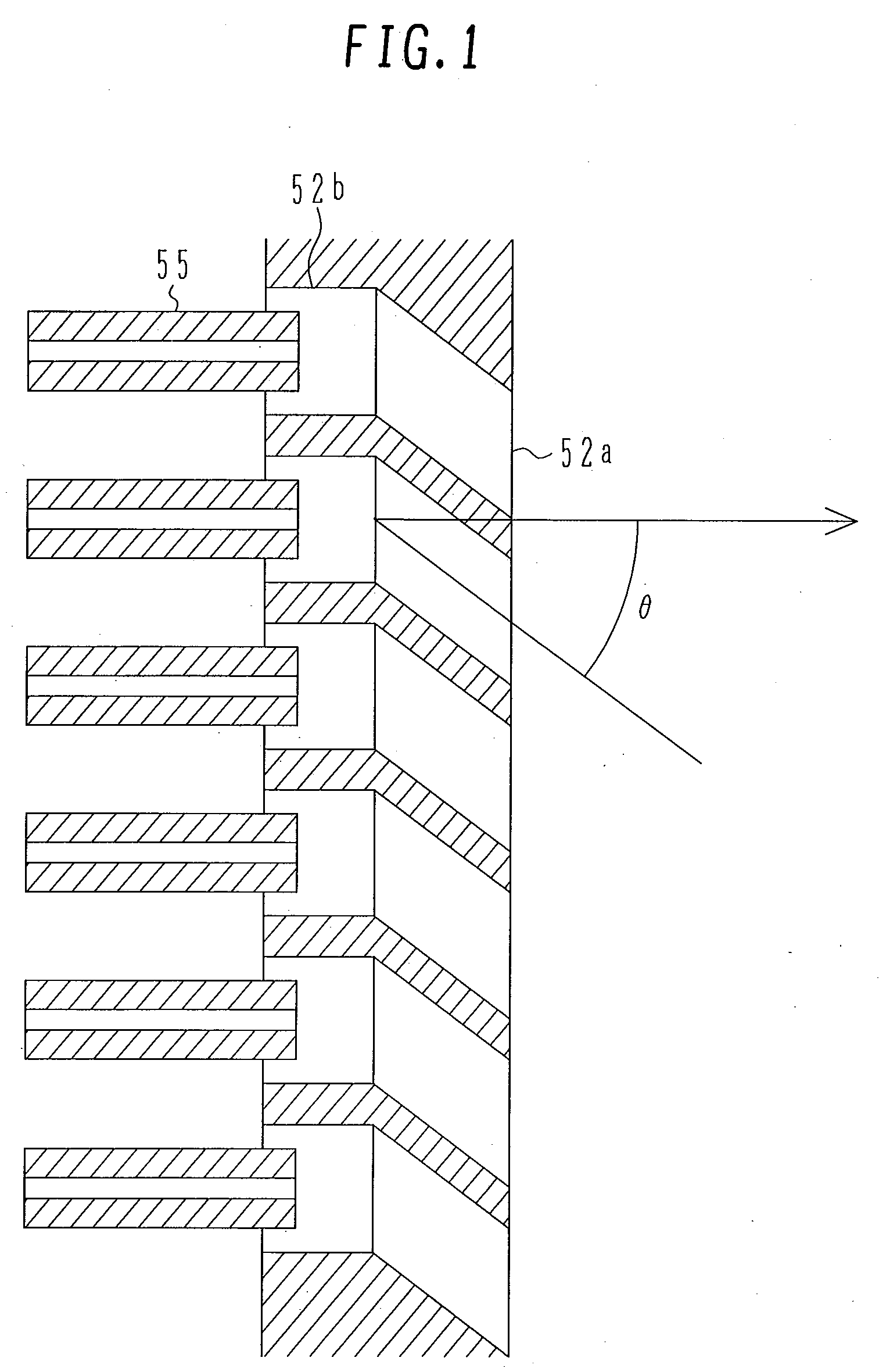
[0040]FIG. 5 is a developed view of air nozzles according to a second embodiment of the present invention. The second embodiment is different from the first embodiment in that the member which constitutes a straight portion 52b is a member separate from the member which constitutes a slant portion 52a. In the first embodiment a bent portion is present halfway of the air flow path and is considered to make the fabrication thereof somewhat difficult. In this second embodiment, since the slant portion is constituted by a member separate from the straight portion, an advantage that the respective fabrications are easy is achieved. Both members can be united and installed by not only such a mechanical joining method as bolting but also such a technique as welding or diffusion bonding.
third embodiment
[0041]FIG. 6 illustrates a third embodiment of the present invention. The third embodiment is different from the first and second embodiments in that straight portions 52b are formed for only such slant portions 52a as are given a rotational angle. More specifically, of three rows of air nozzles formed concentrically in an air nozzle plate, the air nozzles located in the second and third rows with respect to the plate center are each provided with only a straight portion, while the air nozzles located in the first row from the plate center are each provided with both straight portion and slant portion successively from the upstream side. Therefore, a look at a sectional view (the left side in FIG. 6) of air nozzles taken along a plane including the plate center shows that air flow paths in the first row of air nozzles are formed longer than those in the second and third rows of air nozzles. Moreover, fuel nozzle-side wall surfaces in the first row of air nozzles are positioned on th...
PUM
 Abstract
Description
Claims
Application Information
 - R&D
- Intellectual Property
- Life Sciences
- Materials
- Tech Scout
- Unparalleled Data Quality
- Higher Quality Content
- 60% Fewer Hallucinations
Browse by: Latest US Patents, China's latest patents, Technical Efficacy Thesaurus, Application Domain, Technology Topic, Popular Technical Reports.
© 2025 PatSnap. All rights reserved.Legal|Privacy policy|Modern Slavery Act Transparency Statement|Sitemap|About US| Contact US: help@patsnap.com


