Cutting Wheel with Disposable Blade

a cutting wheel and blade technology, applied in shearing tools, metal-working equipment, shearing equipment, etc., can solve the problems of expensive manufacturing and replacement of cutting wheels when worn, and achieve the effects of reducing manufacturing costs, reducing manufacturing costs, and reducing production costs

Inactive Publication Date: 2009-12-03
EMT INT CO LTD
View PDF18 Cites 29 Cited by
  • Summary
  • Abstract
  • Description
  • Claims
  • Application Information

AI Technical Summary

Benefits of technology

[0005]However, conventional cutting wheels are constructed almost entirely of tool steel making these cutting wheels expensive to manufacture and replace when worn. A disposable, replaceable cutting wheel that is inexpensive to manufacture and replace would, therefore, create further efficiencies in in-line web processing.
[0006]In the present application, a novel cutting wheel has a three part assembly including a disposable blade wheel. The three part wheel assembly comprises an inner support wheel; an outer support wheel; and the disposable blade wheel. In one embodiment, the disposable blade wheel is positioned between the inner support wheel and the outer wheel support hub. This three part assembly then is affixed to an interior hub for rotational movement when mounted on a rotatable shaft of a web cutting machine of the type well known in the art. The disposable blade wheel comprises a circular or disc-type structure wherein only the outer periphery of the wheel is constructed of a cutting material. In one embodiment, the cutting material is hardened tool steel, but the outer periphery may be constructed of any other type of material suitable for cutting a web of material. This outer periphery comprises a cutting edge that will contact a web material for cutting, slitting or otherwise processing a web of material. The disposable blade wheel of the present application has approximately ⅙ the amount of expensive cutting material (e.g. tool steel) than traditional cutting wheels. The disposable blade wheel of the present application is, therefore, less expensive to manufacture and takes far less time to produce.
[0007]In one embodiment, the three part cutting wheel is assembled using low profile bolts that attach through the outer support wheel and the disposable blade wheel to connect the outer support wheel and the disposable blade wheel to the inner support wheel. In one embodiment, the low profile bolts may be tightened and loosened with a tool, such as an Allen wrench a hexagonal wrench or other tool. In another embodiment, the bolts may be loosened and tightened by hand. Openings in the outer support wheel hub to receive the bolts allow for “twist and lock” connection of the three part cutting wheel, wherein when the bolts are loosened, the outer support wheel may be twisted such that bolts fit through the larger portion of the opening and the outer support wheel may be removed to access the disposable blade wheel. Likewise, the disposable blade wheel includes the same type of openings for easy removal. When the outer support wheel and disposable blade wheel are secured to the inner support wheel, the bolts are twisted for placement in the smaller portion of the opening and then are tightened either by tool or by hand.

Problems solved by technology

However, conventional cutting wheels are constructed almost entirely of tool steel making these cutting wheels expensive to manufacture and replace when worn.

Method used


Image

  • Cutting Wheel with Disposable Blade
  • Cutting Wheel with Disposable Blade
  • Cutting Wheel with Disposable Blade

Examples


Embodiment Construction

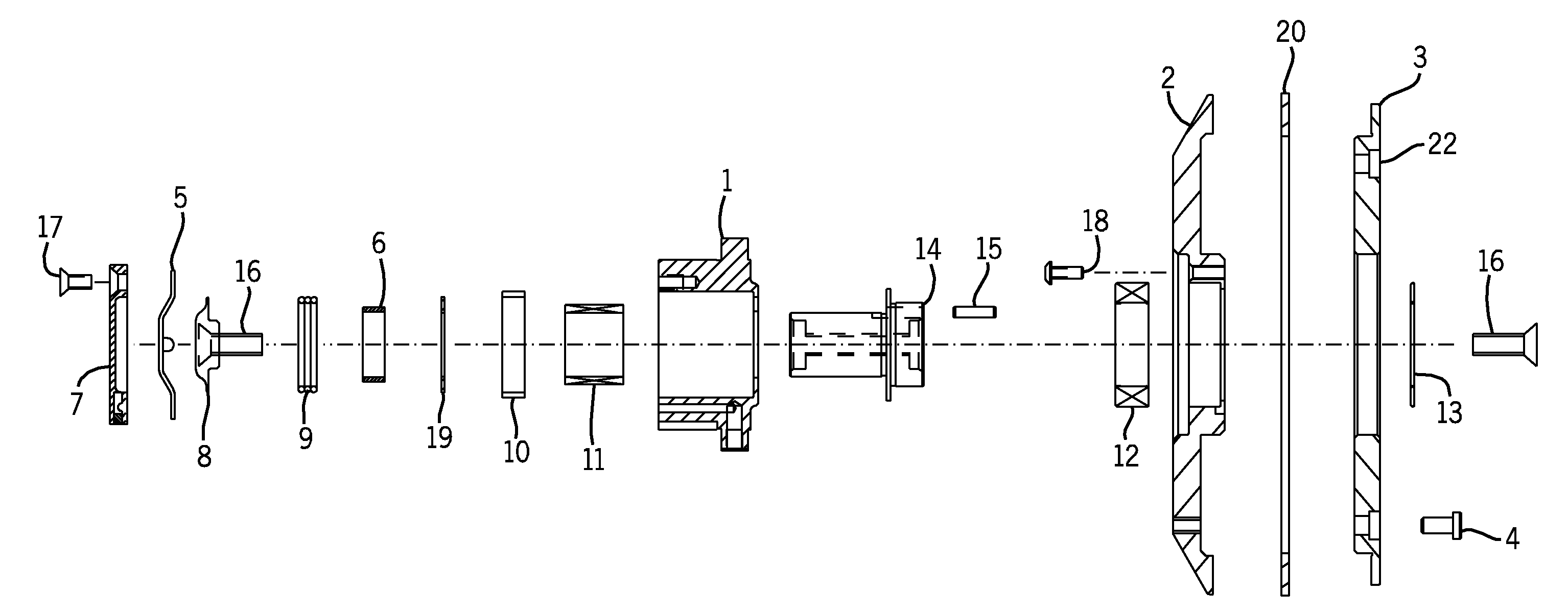
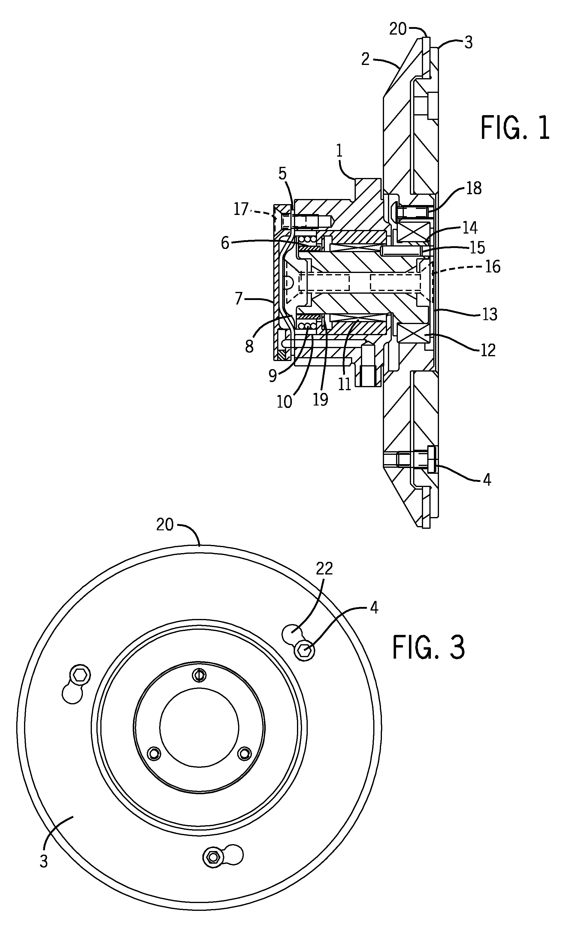
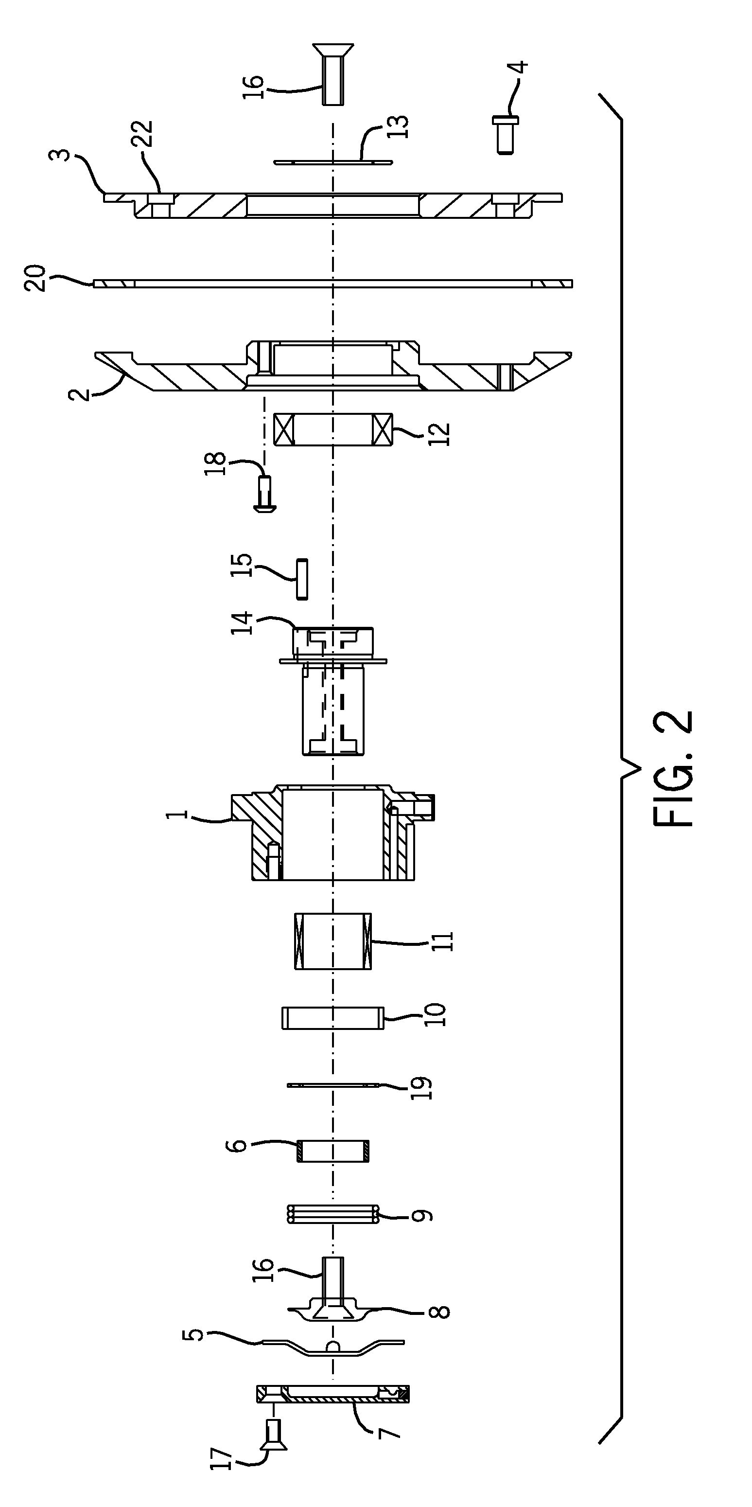
[0013]Turning first to FIG. 1, therein is shown a cross section of the cutting wheel assembly of the present application. The cutting wheel assembly includes an interior hub assembly comprising a holder housing 1, a holder axle 14, a piston 8 and at least one bearing 11. In some embodiments, the interior hub assembly further comprises a combination of spacers 6, 10, washers 19; wave springs 9; and diaphragms 5. The interior hub components are typically secured together with a cap 7 using bolts or screws 17, but may be secured in any other conventional manner, as will be recognized by one or ordinary skill in the art. In some embodiments a diaphragm 5 allows for the previously mentioned items to be secured within the holder housing 1. In that embodiment, end cap 7 secured with bolts or screws 17 (or in another conventional manner) secures the diaphragm 5, a piston 8 with rod 16, a wave spring 9, a spacer 6, a nylon washer 19, another spacer 10 and a bearing 11 in holder housing 1. Th...


PUM

PropertyMeasurementUnit
sizeaaaaaaaaaa
sizeaaaaaaaaaa

Abstract

A cutting wheel having a disposable blade is a constructed of a disposable blade wheel, an inner support wheel and an outer support wheel to define a three part cutting assembly. An interior hub adapted to be mounted to the three part cutting assembly to provide a cutting wheel assembly. The disposable blade wheel is adapted to be connected to the inner support wheel and the outer support wheel, and may be located between the inner support wheel and outer support wheel. In the three part cutting assembly, an outer periphery of the blade wheel extends radially outwardly of an outer periphery of the inner support wheel and of an outer periphery of the outer support wheel to provide a cutting surface having a cutting edge. The cutting edge comprises a cutting material such as hardened tool steel, high carbon steel, non-ferrous alloys or the like. The cutting wheel assembly is adapted to be mounted onto a conventional rotatable shaft of a conventional web processing machine of the types well known in the art to process a web of material.

Description

CROSS-REFERENCE TO RELATED APPLICATIONS[0001]This application claims priority to Provisional Application Ser. No. 61 / 056,711, filed on May 28, 2008.BACKGROUND AND SUMMARY OF THE INVENTION[0002]In the production of paper, film, foil, laminate, plastic, vinyl, rubber, woven and non-woven products, a continuous web of such material passes through an in-line web processing apparatus and, often, the web of material requires separation into distinct sections. In line web-processing machines are well-known in the art, and often utilize a cutting wheel mounted on a rotational shelf for processing a web of material. The present application is directed to a novel cutting wheel for slitting, cutting or otherwise processing a web of material into a plurality of web portions, and particularly to a cutting wheel incorporating a unique, disposable blade wheel in a cutting wheel assembly.[0003]It is often desired to separate a single, wide source web of material into a plurality of relatively narro...

Claims


Application Information

Patent Timeline
Patent Type & Authority Applications(United States)
IPC IPC(8): B26D1/14
CPCB26D7/2621Y10T83/9377Y10T83/9403Y10T83/9464
Inventor RAUSCHER, PAUL D.BAUMGARTNER, BRYAN
Owner EMT INT CO LTD
Why Eureka
Try Eureka