Recuperative Hybrid Trains using Batteries in an intermodal Container

Inactive Publication Date: 2009-12-03
SCHMITZ RUDOLF HARDY
View PDF5 Cites 30 Cited by
  • Summary
  • Abstract
  • Description
  • Claims
  • Application Information

AI Technical Summary

Benefits of technology

[0011]As illustrated in FIG. 1, this invention improves the previous art for hybrid diesel-electric trains by installing such batteries inside standard intermodal containers which are already used in very large quantities worldwide for the transportation of goods and for which cranes are readily available in many places. The containers housing the batteries are standardized, so that different operators can use them by way of purchase or rental. Such battery containers can be placed on a freight train chassis in different configurations as shown in FIG. 2 to allow a variety of ratios between the number of containers and the number of locomotives to accommodate different requirements. The battery containers itself will be equipped with their own ventilation system to prevent overheating or the accumulation of unwanted fumes as well as cables with plugs to connect the container's ba

Problems solved by technology

Its application for heavy trains such as freight trains poses a particular problem, however, in that the combination of the trains high total weight (in excess of a few thousand tons) and occasional but prolonged descents from mountains (elevation decrease of several thousand feet) requires batteries of tremendous weight while commercial applications require that batteries be highly mobile so that they can be used wherever needed

Method used


Image

  • Recuperative Hybrid Trains using Batteries in an intermodal Container
  • Recuperative Hybrid Trains using Batteries in an intermodal Container
  • Recuperative Hybrid Trains using Batteries in an intermodal Container

Examples


Embodiment Construction

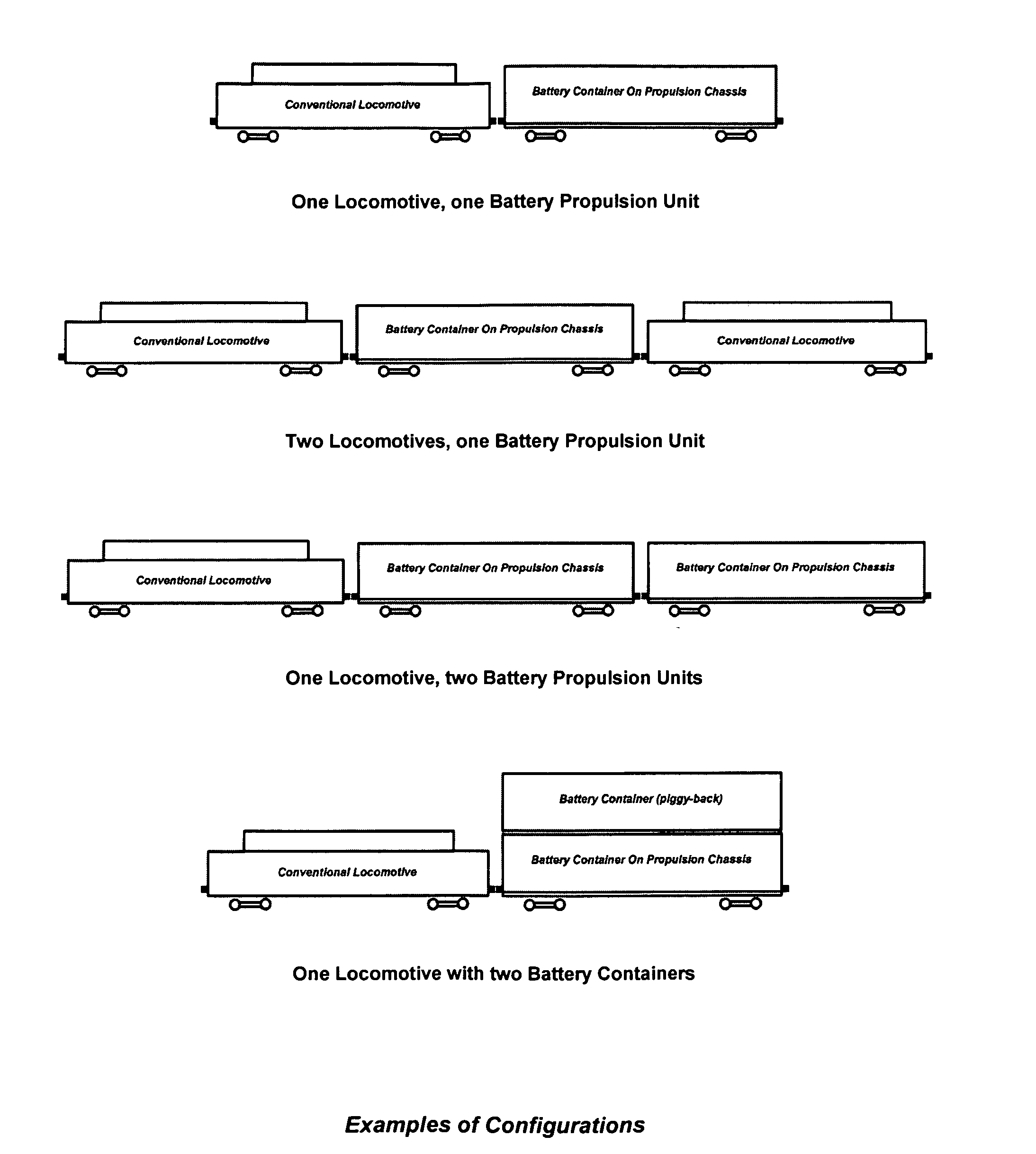
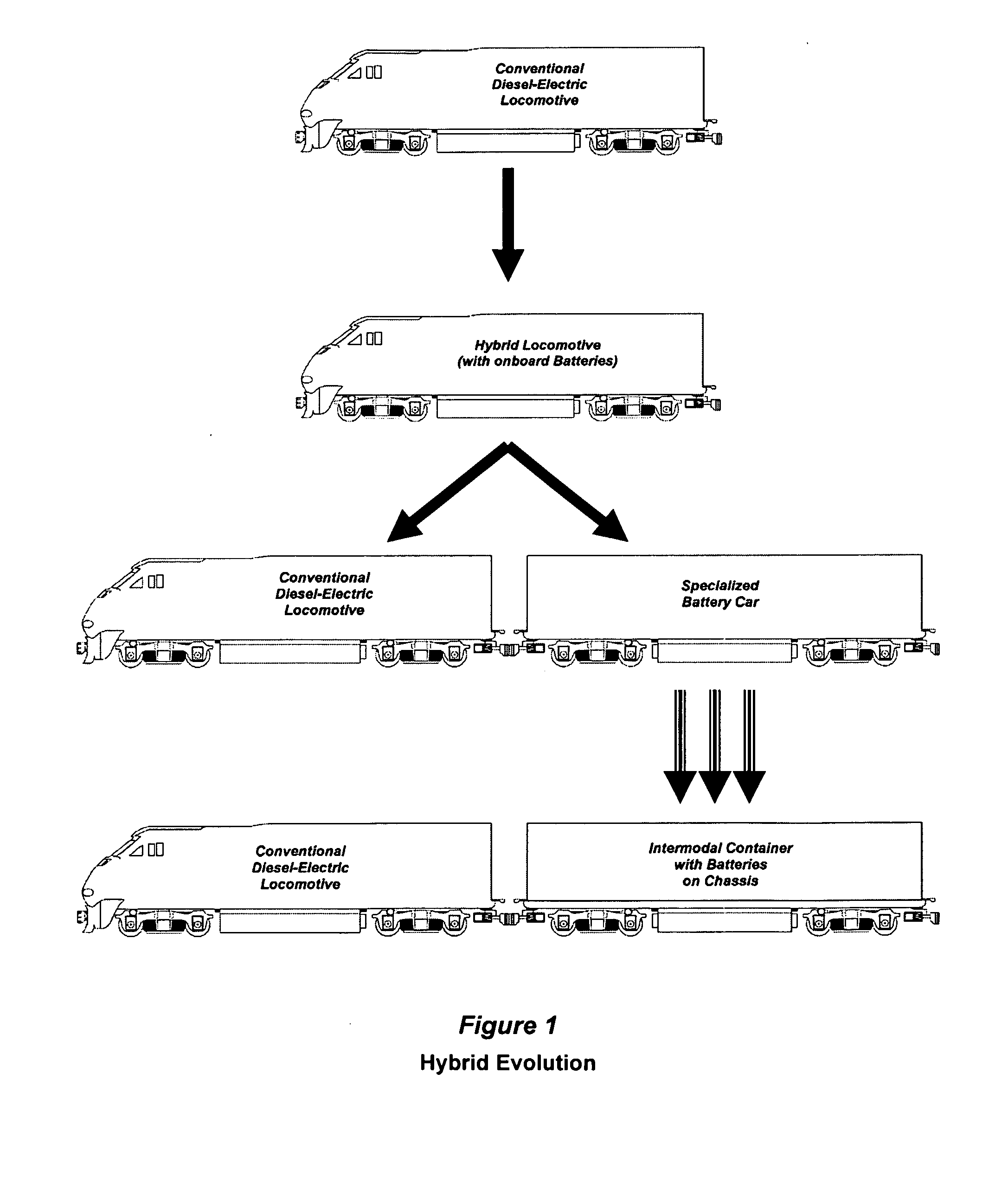
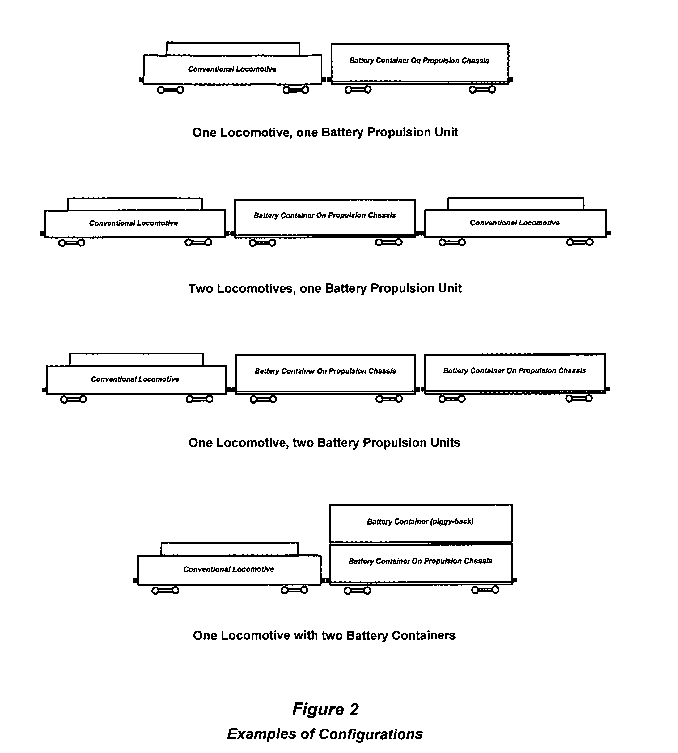
[0016]The present invention relates generally to hybrid versions of diesel-electric locomotives and improves the previous art (see FIG. 1) by placing such batteries in standard intermodal containers (referred to in this document as battery containers) which can easily be moved by readily available cranes built for the purpose of moving freight containers (see FIG. 3). Such battery containers can be placed on a freight train chassis in different configurations (as shown in FIG. 2) to allow a variety of ratios between the number of containers and the number of locomotives to accommodate different requirements. The battery containers itself will be equipped with their own ventilation system to prevent overheating or the accumulation of unwanted fumes as well as cables with plugs to connect the container's batteries to the power grid and information network of the train and / or chassis if a chassis with motors and recuperative brakes is used. The containers will also house the power conv...


PUM


Abstract

The present invention relates generally to hybrid versions of diesel-electric locomotives and improves the previous art by placing such batteries in standard intermodal containers which can easily be moved by readily available cranes built for the purpose of moving freight containers. The containers housing the batteries are standardized, so that different operators can use them by way of purchase or rental. The invention produces the following advantages. (1) After a descent from high altitudes, a full battery unit can be removed from a train and put in storage to reduce the weight of the train should no extra power be needed for the next leg of the journey. On particular long descents, full battery units can be replaced by empty ones several times to enable further energy recovery as the train continues its way down the mountain. (2) Conversely, a train heading for the mountains can be loaded with one or more full battery containers from storage to reduce the use of fossil fuels during the ascent and, if need be, receive replacement units on the way should the original set not last long enough to reach the high point. (3) Different configurations become possible such as two containers, one on top of the other, to accommodate different requirements. (4) The commercial trade of battery containers, made possible through standardization, will create a market for energy which will result in its most efficient use.

Description

CROSS_REFERENCE TO RELATED APPLICATIONS [0001]Not ApplicableSTATEMENT REGARDING FEDERALLY SPONSORED RESEARCH OR DEVELOPMENT[0002]No federally sponsored research or development was requested or received.REFERENCE TO SEQUENCE LISTING[0003]No material is submitted separately on a compact disk.BACKGROUND OF THE INVENTION[0004]With the advent of high capacity batteries (30 Watt Hours or more per pound of weight) which are also capable of being rapidly charged and discharged (80% in less than five minutes), the concept of recovering kinetic and potential energy of a moving vehicle for future use (hybrid systems) will increasingly be used in automobiles, trains and other vehicles. Its application for heavy trains such as freight trains poses a particular problem, however, in that the combination of the trains high total weight (in excess of a few thousand tons) and occasional but prolonged descents from mountains (elevation decrease of several thousand feet) requires batteries of tremendou...

Claims


Application Information

Patent Timeline
IPC IPC(8): B61C3/00
CPCB60L9/00B60L11/1822B61C3/02B61C7/04Y02T10/7005B60L2200/26Y02T10/92Y02T30/16Y02T90/124Y02T90/14Y02T10/7072B60L53/80Y02T30/00Y02T10/70Y02T90/12
Inventor SCHMITZ, RUDOLF HARDY
Owner SCHMITZ RUDOLF HARDY
Why Eureka
Try Eureka