Submarine with a propulsion drive with an electric motor ring

a propulsion drive and electric ring technology, applied in underwater equipment, special-purpose vessels, vessel construction, etc., can solve the problems of easy loss of the submarine, easy to locate the submarine, and poor propulsion drive efficiency, so as to achieve good propulsion drive efficiency, increase the power output of the propulsion drive, and avoid cavitation and undesired noise scan

Active Publication Date: 2009-12-03
SIEMENS ENERGY GLOBAL GMBH & CO KG
View PDF6 Cites 20 Cited by
  • Summary
  • Abstract
  • Description
  • Claims
  • Application Information

AI Technical Summary

Benefits of technology

[0024]The stern cone can also extend into the propulsion drive or can extend through the propulsion drive. The stern cone is then preferably arranged in a line with the axis of rotation of the rotor or of the rotors of the propulsion drive. Preferably the stern cone in such cases is symmetrical to the axis, with its axis of symmetry running in a line with the axis of rotation of the rotor or of the rotors. The ends of the blades of the rotor or of the rotors can in such cases also be supported to rotate on the stern cone, which enables the stability and thereby the power output of the propulsion drive to be increased. Alternately the e

Problems solved by technology

A disadvantage with this type of propulsion drive is the relatively large noise radiation of the propeller which makes it easier to locate the submarine.
In addition at great depths even a small amount of damage to the shaft seal can lead to problems for the submar

Method used


Image

  • Submarine with a propulsion drive with an electric motor ring
  • Submarine with a propulsion drive with an electric motor ring
  • Submarine with a propulsion drive with an electric motor ring

Examples


Embodiment Construction

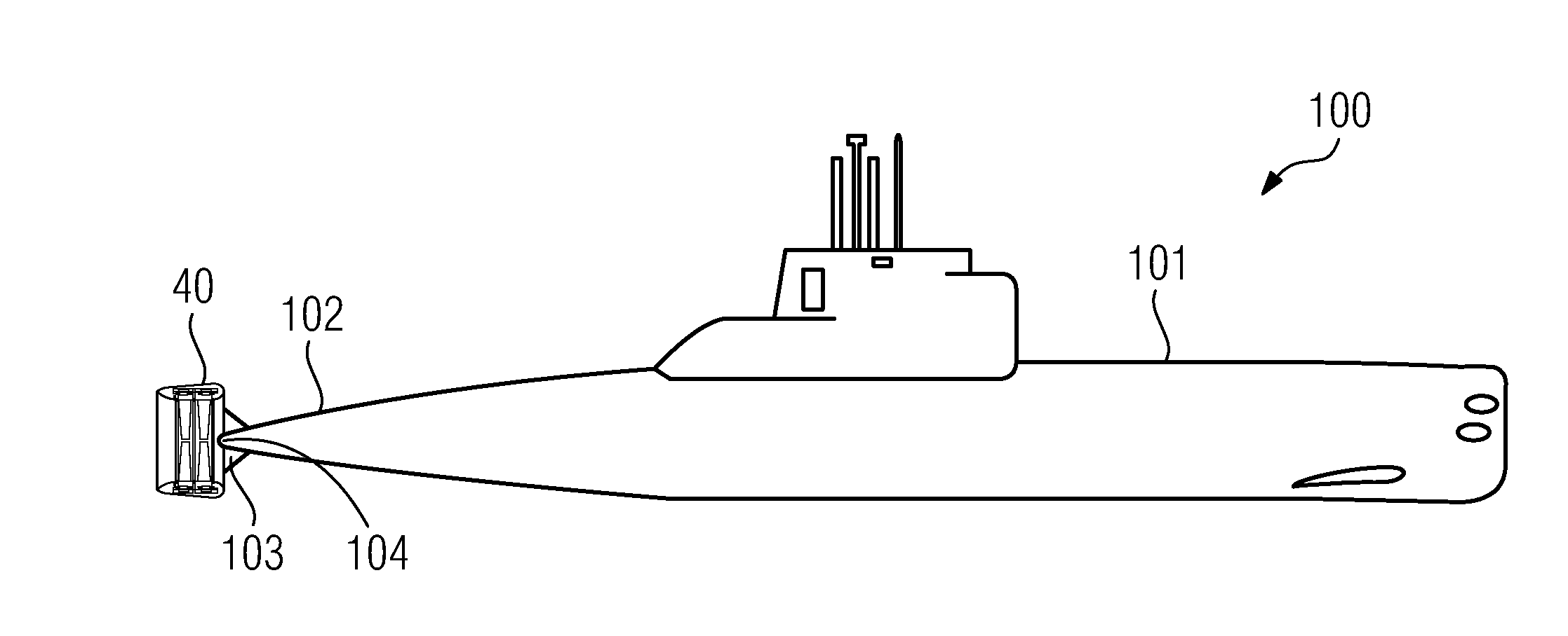
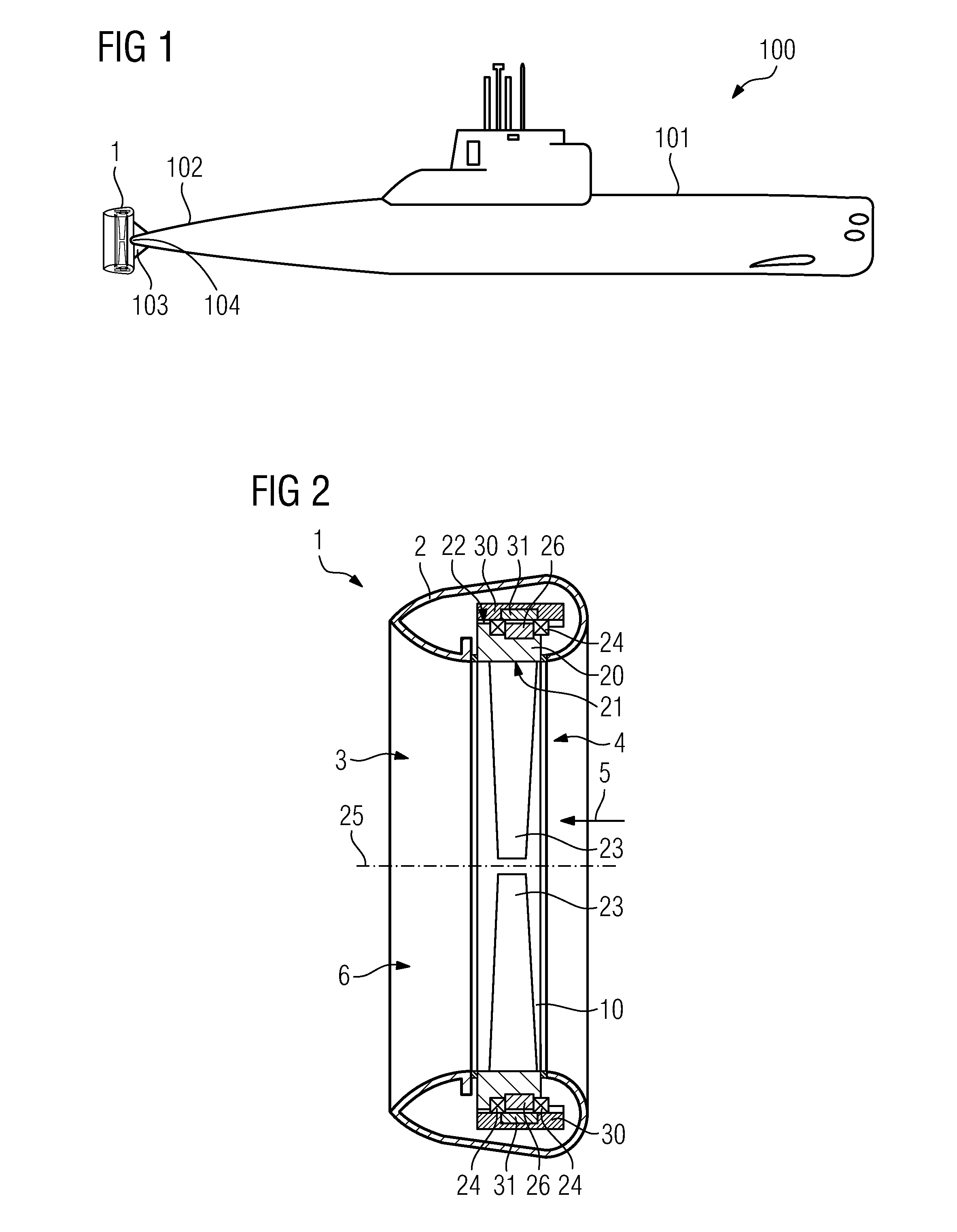
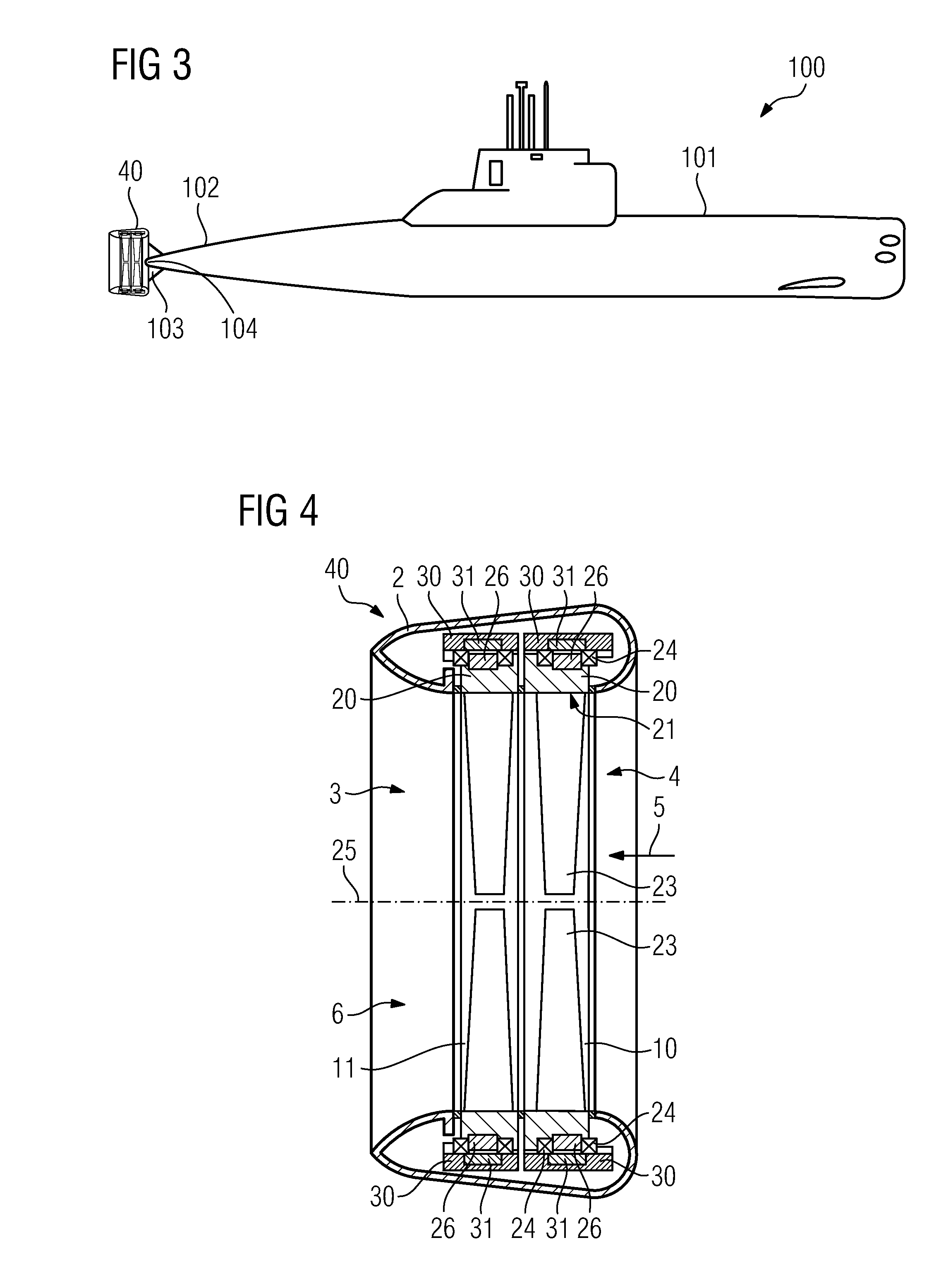
[0040]FIG. 1 shows in a basic diagram a manned military submarine 100 with a boat hull and a propulsion drive 1 arranged at the stern 102 of the submarine 100. The propulsion drive 1 in this case represents the main propulsion drive of the submarine. The propulsion drive 1 is arranged in the longitudinal direction of the submarine 100 as an extension of the stern outside the boat hull 101. The propulsion drive 1 is attached to the boat hull 101 by means of holders 103. Basically a submarine can also have two or more of such propulsion drives 1 as its main propulsion drive, which are arranged in the longitudinal direction of the submarine 100 as an extension of the stern 102 outside the boat hull 101 (e.g. one each on the starboard and port side).

[0041]As shown in detail in FIG. 2, the main propulsion unit 1 features a housing 2 embodied in the shape of a nozzle, which forms a tubular channel 3 for a flow of water through the channel 3 in a main direction of flow 5 from an inlet 4 to...


PUM


Abstract

In one aspect, a submarine with a boat hull and a propulsion drive for the submarine the propulsion drive is arranged outside the boat hull and comprises a housing and a first electric motor, with the housing embodying a channel for a flow of water through the channel in a main direction of flow from an inlet to an outlet of the channel, and with the first electric motor featuring a rotor which is arranged in the channel and is supported rotatably around an axis of rotation in the housing, with the rotor being embodied in the shape of a ring with a ring inner side and a ring outer side, and with blades for propelling the submarine being arranged on the ring inner side of the rotor.

Description

CROSS REFERENCE TO RELATED APPLICATIONS[0001]The present application claims the benefit of the provisional patent application filed on Jun. Nov. 21, 2008, and assigned application No. 61 / 116,652, to the German application No. 10 2008 025 211.5 DE filed May 27, 2008. All of the priority applications are incorporated by reference herein in their entirety.FIELD OF INVENTION[0002]The invention relates to a submarine with a propulsion drive with an electric ring motor.BACKGROUND OF INVENTION[0003]Current manned military submarines usually have an electric motor arranged in the submarine as their propulsion drive, which via a propeller shaft drives a propeller arranged in a longitudinal direction outside the hull of the boat as an extension of the stern. To this end the propeller shaft must penetrate the hull of the submarine in the submarine's stern. The sealing at the point of penetration is provided in such cases by a shaft sealing ring. With some types of submarine two propeller shaft...

Claims


Application Information

Patent Timeline
IPC IPC(8): B63G8/08H02K21/14
CPCB63G8/08B63H1/16H02K7/14B63H2001/165B63H2023/005B63H21/17B63H23/24
Inventor SCHRODER, DIERK
Owner SIEMENS ENERGY GLOBAL GMBH & CO KG
Why Eureka
Try Eureka