
Laser manufacturing system having real-time feedback

a manufacturing system and real-time feedback technology, applied in the field of laser manufacturing systems, can solve the problems of increasing the number of components required to complete the process and the difficulty of controlling those components, and the monitoring effect of the monitoring cannot be observed on the quality of the created holes

Inactive Publication Date: 2009-12-03
CATERPILLAR INC
View PDF30 Cites 6 Cited by
  • Summary
  • Abstract
  • Description
  • Claims
  • Application Information

AI Technical Summary

Problems solved by technology

Although the laser drilling process described in the '406 publication may be capable of monitoring the breakthrough of a laser beam during hole creation, the process may be complicated and have limited benefit.
Specifically, the process utilizes two light sources (i.e., the laser beam and the measuring beam), which increases the number of components required to complete the process and the difficulty of controlling those components.
In addition, although hole creation may be monitored by the process described in the '406 publication, little effect of the monitoring can be observed on the quality of the created hole.

Method used


Image

  • Laser manufacturing system having real-time feedback
  • Laser manufacturing system having real-time feedback
  • Laser manufacturing system having real-time feedback

Examples


Embodiment Construction

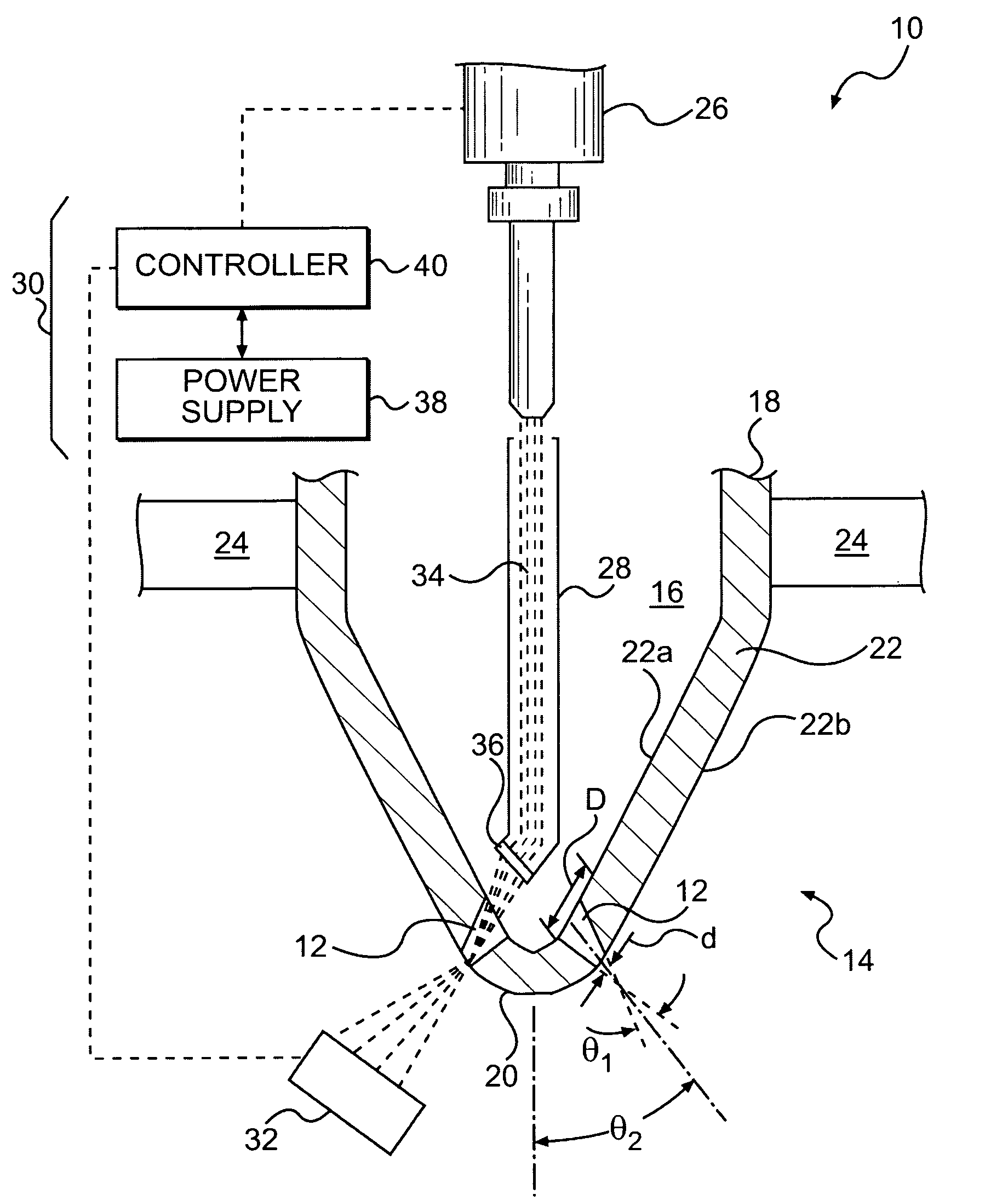
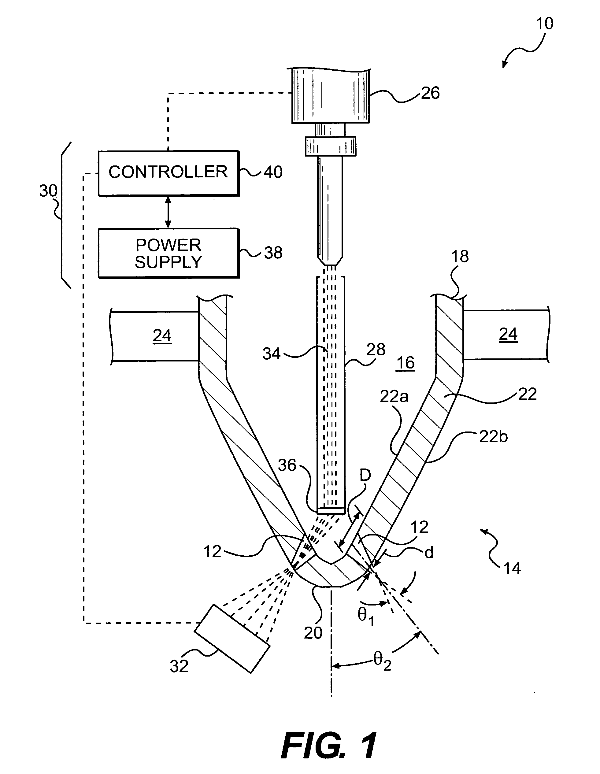
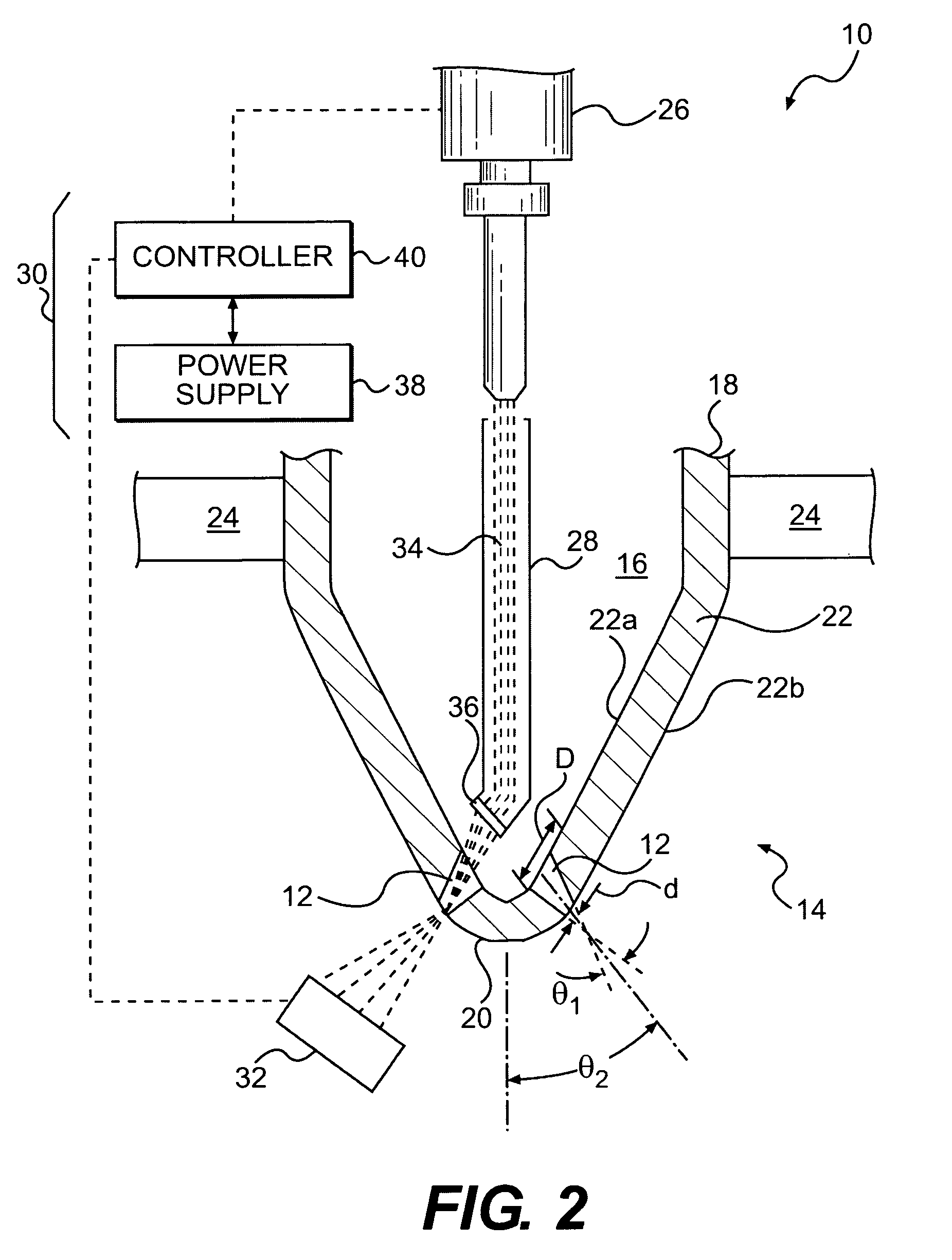
[0011]FIG. 1 illustrates a manufacturing system 10 used to create one or more features 12 within a workpiece 14. In one example, workpiece 14 may be a fuel injector nozzle, for example a high pressure fuel injector nozzle for use with a common rail fuel system (not shown). As a fuel injector nozzle, workpiece 14 may be generally hollow, having an internal axial bore 16 that extends from a base end 18 toward a tip end 20. One of features 12 may be, for example, an injection orifice passing through a side wall 22 of workpiece 14 at tip end 20. To improve a flow of fuel from bore 16 into a combustion chamber (not shown) of an associated combustion engine (not shown), each injection orifice may have a reverse taper profile. That is, each orifice may be generally circular in cross-section and have a diameter “D” at an internal surface 22a of wall 22 that is greater than a diameter “d” at an external surface 22b of wall 22 such that a cross-sectional flow area of the orifice decreases in ...


PUM

PropertyMeasurementUnit
taper angleaaaaaaaaaa
droop angle θ2aaaaaaaaaa
wavelengthaaaaaaaaaa

Abstract

A manufacturing system is disclosed. The manufacturing system may have a mount configured to hold a workpiece, a laser source configured to generate a laser beam directed toward a first side of the workpiece, and a sensor located on a second side of the workpiece. The sensor may be configured to sense a characteristic of the laser beam during penetration of the workpiece and to generate a signal in response thereto. The manufacturing system may also have a controller in communication with the laser source and the sensor. The controller may be configured to adjust parameters of the laser beam during penetration of the workpiece based on the signal.

Description

TECHNICAL FIELD[0001]The present disclosure relates to a laser manufacturing system and, more particularly, to a laser manufacturing system having real-time feedback.BACKGROUND[0002]A fuel injector can be used to inject high pressure fuel into a cylinder of a combustion engine. Specifically, a tip of the fuel injector has one or more small orifices disposed therein and, as the high pressure fuel is directed into the fuel injector, it passes to the cylinder by way of these orifices. To enhance operation of the combustion engine, the orifices are precisely formed to have a particular profile and opening diameters.[0003]One way to produce high-precision orifices is through laser machining. Specifically, laser machining involves the use of a laser to melt, vaporize, and / or ablate micro-craters within the fuel injector in a controlled fashion. To help ensure that the resulting crater geometry matches a desired geometry without causing damage to the component or the surroundings, care sho...

Claims


Application Information

Patent Timeline
Patent Type & Authority Applications(United States)
IPC IPC(8): B23K26/00B23P15/00
CPCB23K26/03B23K26/388Y10T29/49428F02M61/1846F02M61/168B23K26/389
Inventor HU, ZHAOLIGRANT, JR., MARION B.
Owner CATERPILLAR INC
Learn More