Pull actuated foam pump

a foam pump and push bar technology, applied in the field of push bar pump, can solve the problems of limiting the industrial design options of push bar shape, increasing dispenser production costs, and waste of either produ

Inactive Publication Date: 2009-12-03
GOJO IND INC
View PDF59 Cites 29 Cited by
  • Summary
  • Abstract
  • Description
  • Claims
  • Application Information

AI Technical Summary

Benefits of technology

[0008]In accordance with an embodiment of this invention, a refill unit is provided for a dispenser. The refill unit includes a container holding liquid and a pump secured to the container. The pump includes a piston housing secured to the container, and a piston assembly is received in the piston housing so as to reciprocate between a non-actuated position and an actuated position relative thereto, the movement from the non-actuated position to the actuated position serving to dispense the liquid at an outlet of the pump, wherein the piston assembly is moved from the non-actuated position to the actuated position by being pulled in a direction away from the container.
[0009]In accordance with another embodiment of this invention a dispenser is provided having a dispenser housing that selectively receives a refill unit. The refill unit includes a container holding a liquid, the container including a neck extending from a shoulder. The container is received in the housing with the neck positioned below the shoulder. The refill unit also includes a piston housing secured to the container at the neck and extending into the neck to provide an inner wall defining a passageway communicating with the liquid in the container at an inlet end thereof, the inlet end being positioned within the neck such that the piston housing does not extend beyond the shoulder, thus permitting liquid to occupy at least a portion of the neck. The refill unit further includes a piston assembly received by the piston housing so as to reciprocate between a non-actuated position and an actuated position relative thereto to dispense the liquid, wherein the piston assembly does not extend beyond the shoulder, thus permitting liquid to occupy at least a portion of the neck.
[0010]In accordance with an embodiment of this invention a foam dispenser is provided having a dispenser housing that selectively receives a refill unit. The dispenser includes a collapsible air chamber mounted to the dispenser housing and including an air outlet, the collapsible air chamber having an expanded volume and a compressed volume. The refill unit includes a container, a piston housing, a piston assembly, a liquid chamber seal, a premix chamber, and a mesh screen. The piston housing is secured to the container and provides an inner wall defining an axial passageway having an inlet end communicating with liquid held in the container. The piston assembly is received by the piston housing so as to reciprocate between a non-actuated position and an actuated position relative thereto. The piston assembly includes a liquid piston that reciprocatingly fits within the axial passageway of the piston housing, and a piston head extends from the liquid piston and sealingly engages the inner wall of the piston housing. The liquid chamber seal extends between the liquid piston and the inner wall of the piston housing, and the liquid piston, the piston head, the inner wall and the seal define an annular collapsible liquid chamber having an expanded volume and a compressed volume. Positioning the refill unit in the dispenser housing forms an extrusion chamber, and the air outlet of the collapsible air chamber communicates with the extrusion chamber. The premix chamber communicates with the extrusion chamber through extrusion passages. When the piston assembly is moved from the non-actuated position to the actuated position, the annular collapsible liquid chamber is compressed from its expanded volume to its compressed volume, such that liquid therein is advanced to the extrusion chamber; the collapsible air chamber is compressed from its expanded volume to its compressed volume, such that air is advanced to the extrusion chamber to mix with liquid therein; and air and foamable liquid mixed at the extrusion chamber are advanced to the premix chamber through the extrusion passages, with the advancement therethrough further mixing the air and foamable liquid to create a coarse foam, wherein the coarse foam is advanced through the mesh screed to create a more homogenous foam.

Problems solved by technology

This is particularly problematic when a foamed soap is dispensed, because the foam stream exiting the dispensing spout tends to spread in width and flutter side-to-side due to the physical forces acting to create the foam and the properties of the foam itself.
It is somewhat common to modify the shape of the push bar to prevent the push bar from getting too close to the erratic path of the foamed soap, but such modifications can increase dispenser production costs and limit the industrial design options for the push bar shape.
Additionally, because these pumps must have an inlet communicating with the product in the container in order to draw the product into the pump, either product is wasted when the level of the product falls below the inlet to the pump or special adaptations must be made to place the inlet to the pump at a position where the vast majority of the contents of the container can be drawn into the pump.
It has been found that providing the air pump portion as part of the foam pump carried by the refill unit is not necessarily cost effective.
The air pump portion adds to the size, weight and cost of the refill unit, especially in high output dispensers.

Method used


Image

  • Pull actuated foam pump
  • Pull actuated foam pump
  • Pull actuated foam pump

Examples


Embodiment Construction

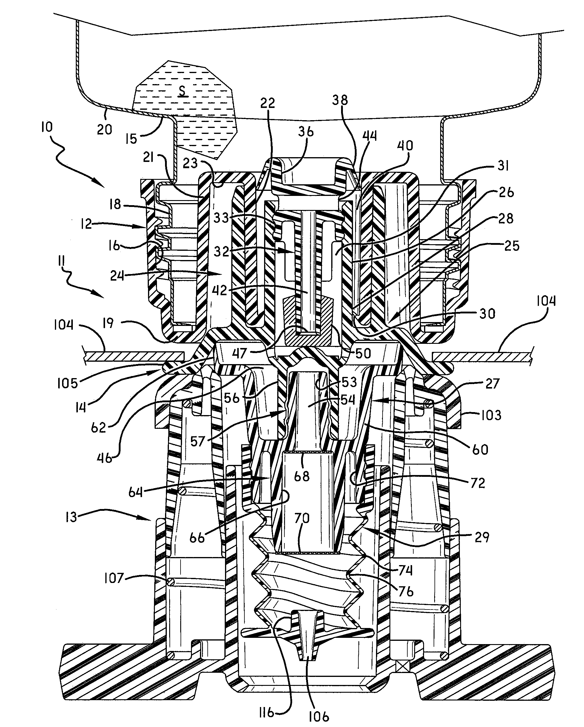
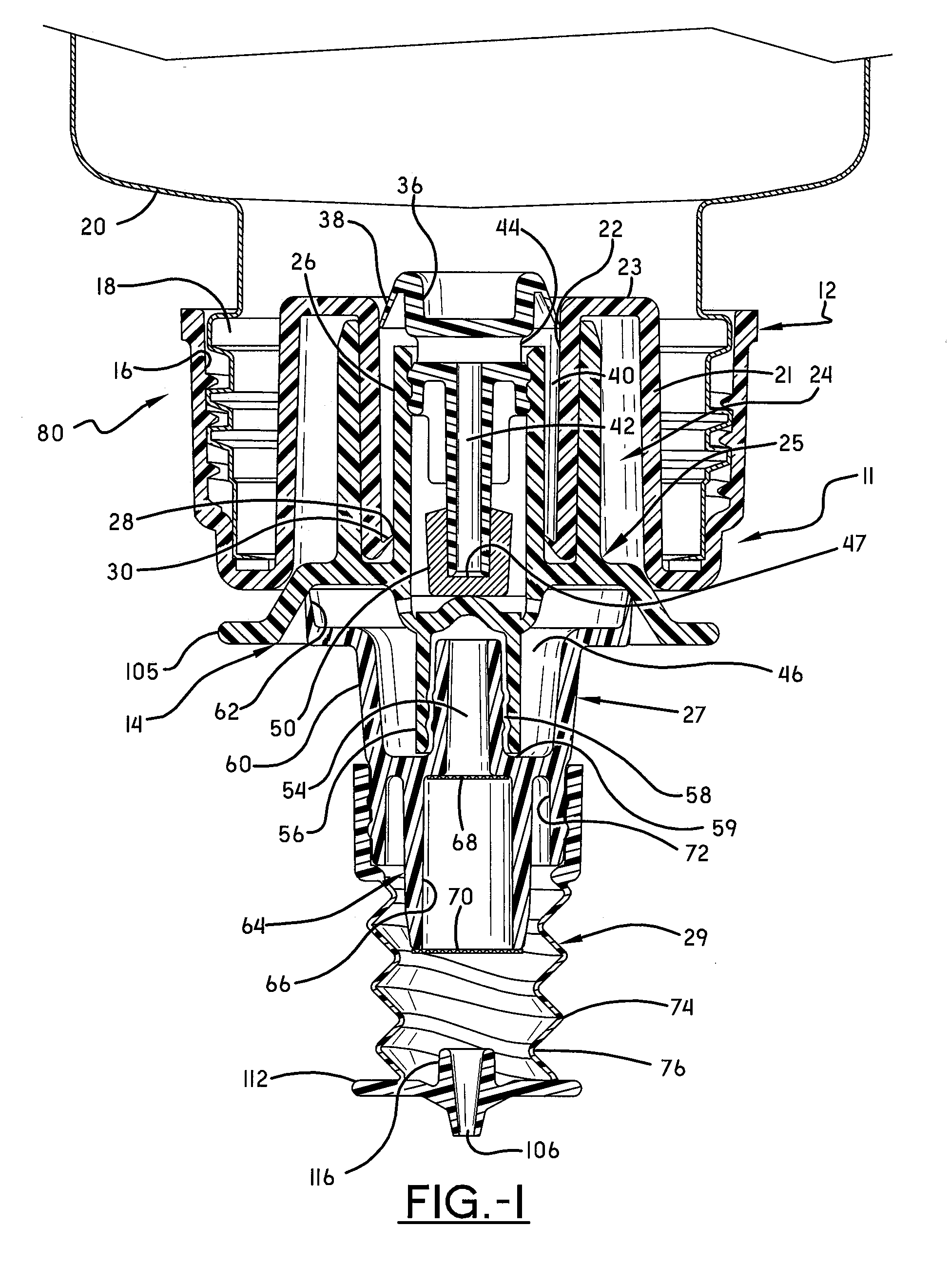
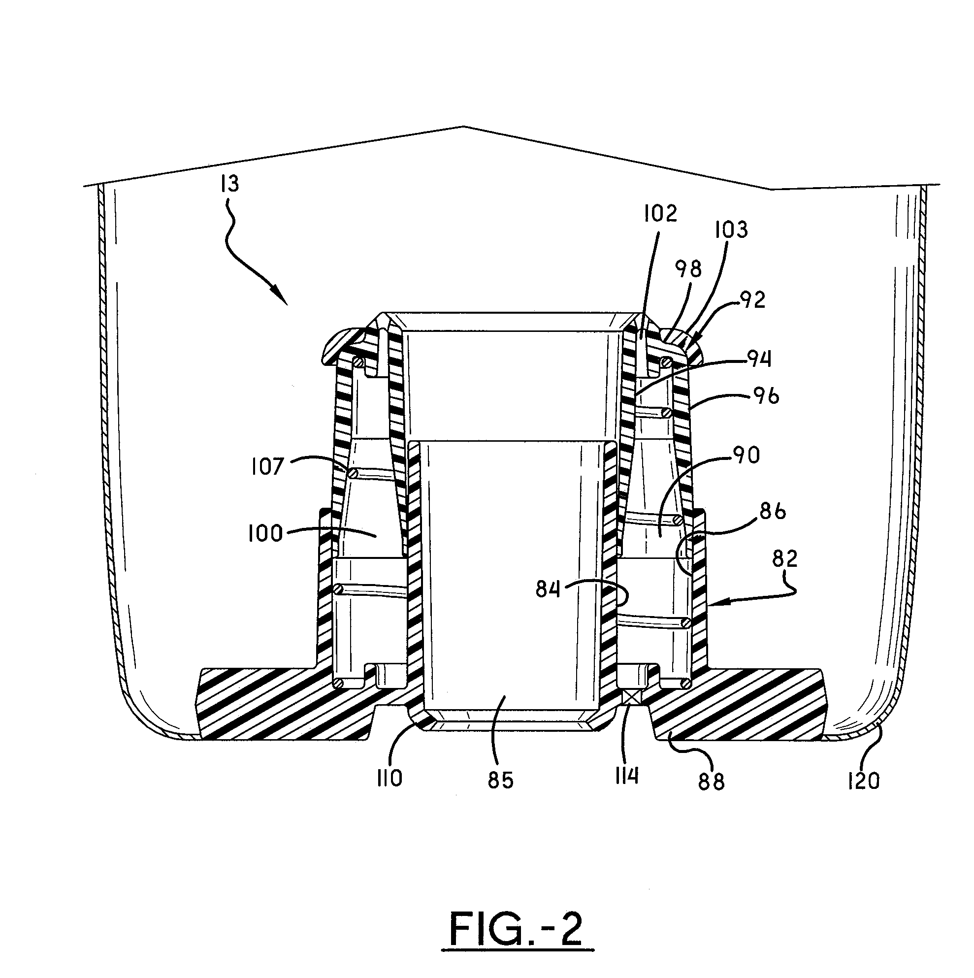
[0015]Referring to FIGS. 1-3, a foam pump 10 (FIG. 3) in accordance with this invention is shown as including a liquid pump portion 11 (FIG. 1) and an air pump portion 13 (FIG. 2). The liquid pump portion 11 is first considered, and includes a piston housing 12, which is joined with a piston assembly 14 such that the piston assembly 14 can selectively reciprocate relative to the piston housing 12, between a rest position (FIG. 3) and an actuated position (FIG. 4), with the understanding that FIG. 4 shows the pump 10 in a fully actuated position, and the pump 10 is actuated upon the initiation or movement from the position of FIG. 3 toward the position of FIG. 4. The piston housing 12 communicates with a source of a foamable liquid, and the pump 10 is actuated to mix the foamable liquid with air and dispense it as foam. In this embodiment, the piston housing 12 includes a threaded sidewall 16 that mates with a threaded neck 18 of a bottle 20 that carries the foamable liquid S. The pi...


PUM


Abstract

A foam dispenser includes a refill unit and a dispenser housing. The refill unit carries foamable liquid and provides a liquid pump portion actuated to advance foamable liquid through the dispenser. The dispenser housing provides an air pump portion actuated to advance air through the dispenser. The air pump portion communicates with the liquid pump portion when the refill unit is properly placed in the housing. The liquid pump portion includes a piston housing that reciprocally receives a piston assembly to define a collapsible liquid chamber. Similarly, the air pump portion includes a piston housing that reciprocally receives a piston assembly to define a collapsible air chamber. Upon actuation of the dispenser, both the liquid chamber and the air chamber collapse and thereby feed air and liquid to an extrusion chamber, and extrude the mixture of air and liquid therein through a premix chamber and at least one mesh screen. The pump is actuated my pulling the piston assembly away from the piston housing, and this is particularly advantageous in the art of wall-mounted dispensers employing push bars typically moved horizontally toward a foam pump to actuate the same.

Description

PRIORITY STATEMENT[0001]This application gains the benefit of U.S. Provisional Application No. 61 / 130,191 filed May 29, 2008, which is incorporated herein by reference.FIELD OF THE INVENTION[0002]The invention herein resides in the art of foam dispensers wherein a foamable liquid and air are combined to dispense a foam product. More particularly, the invention relates to a foam dispenser wherein a liquid pump is provided as part of a disposable refill unit containing the liquid, and an air pump is provided as part of the dispenser housing. This invention further relates to a refill unit having a liquid pump that is actuated upon a pull stroke.BACKGROUND OF THE INVENTION[0003]Most wall mounted soap dispensers include a housing, which is adapted to retain a refill unit including a container of soap and associated pump mechanisms that dispense soap through a dispensing spout upon their actuation. The housing is mounted to a wall, and the pump mechanisms are actuated through movement of...

Claims


Application Information

Patent Timeline
Patent Type & Authority Applications(United States)
IPC IPC(8): B67D5/58B65D37/00B67D7/76
CPCA47K5/14B05B7/0037B05B11/3047B05B11/3097B05B11/3074B05B11/3087B05B11/3052B05B11/1052B05B11/1047B05B11/1074B05B11/1097B05B11/1087
Inventor CIAVARELLA, NICK EHAYES, DAVID D.
Owner GOJO IND INC
Why Eureka
Try Eureka