Ultra high frequency planar antenna

a planar antenna, ultra-high frequency technology, applied in the direction of antennas, antenna details, antenna feed intermediates, etc., can solve the problem of relatively weak backscattered signal from the tag

Inactive Publication Date: 2009-12-03
NAT TAIWAN UNIV OF SCI & TECH
View PDF4 Cites 30 Cited by
  • Summary
  • Abstract
  • Description
  • Claims
  • Application Information

AI Technical Summary

Benefits of technology

[0006]Briefly summarized, an ultra high frequency planer antenna comprises a first plane, a second plane opposite to and separated from the first plane by a gap, a driven dipole disposed on the second plane, a parasitic element disposed on the second plane, and a balun. The balun comprises a coplanar strip line and a microstrip line which has a first strip, a second strip area parallel to the first strip, and a third strip perpendicular to the first and second strip, the coplanar strip line coupled to a truncated ground plane. A width of the microstrip line is 2 mm. The coplanar strip line is disposed on the second plane. The microstrip line is disposed on the first plane. The second plane is separated from the first plane by the gap of 1 mm.
[0007]According to the present invention, an ultra high frequency planer antenna comprises a first plane, a second plane opp

Problems solved by technology

It is because in such a system the backscattered signal from the tag is relatively weak, a

Method used


Image

  • Ultra high frequency planar antenna
  • Ultra high frequency planar antenna
  • Ultra high frequency planar antenna

Examples


Embodiment Construction

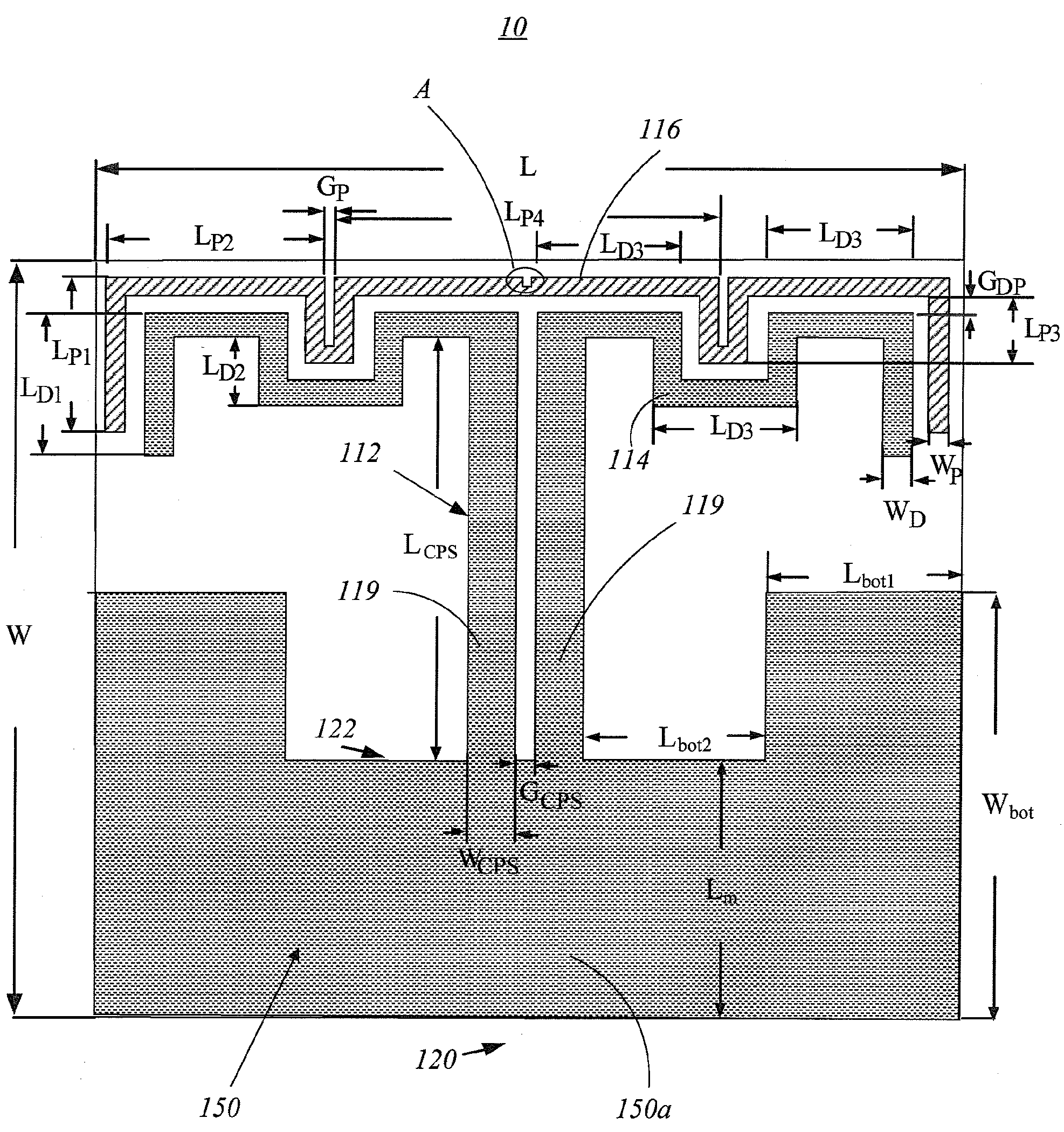
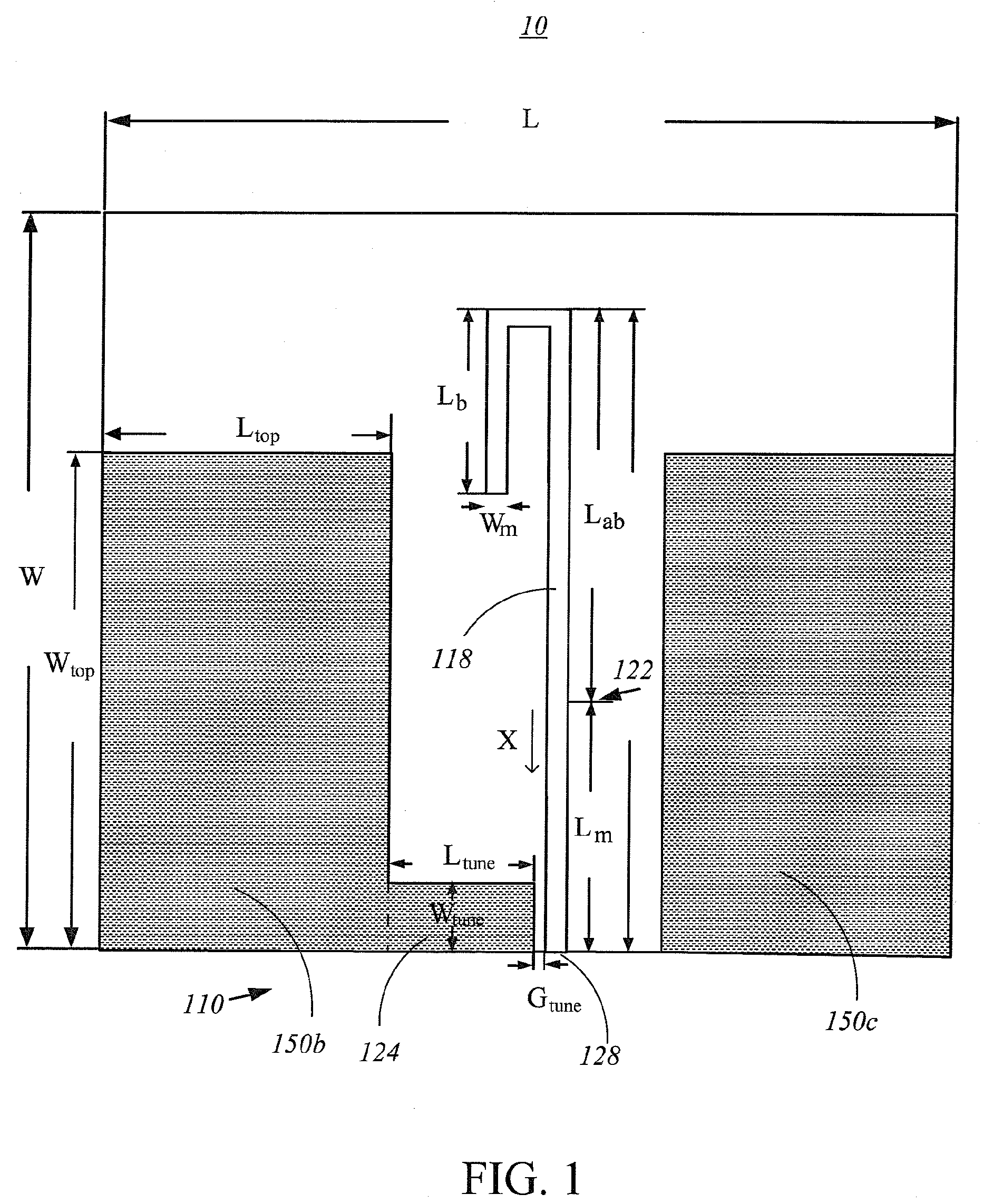
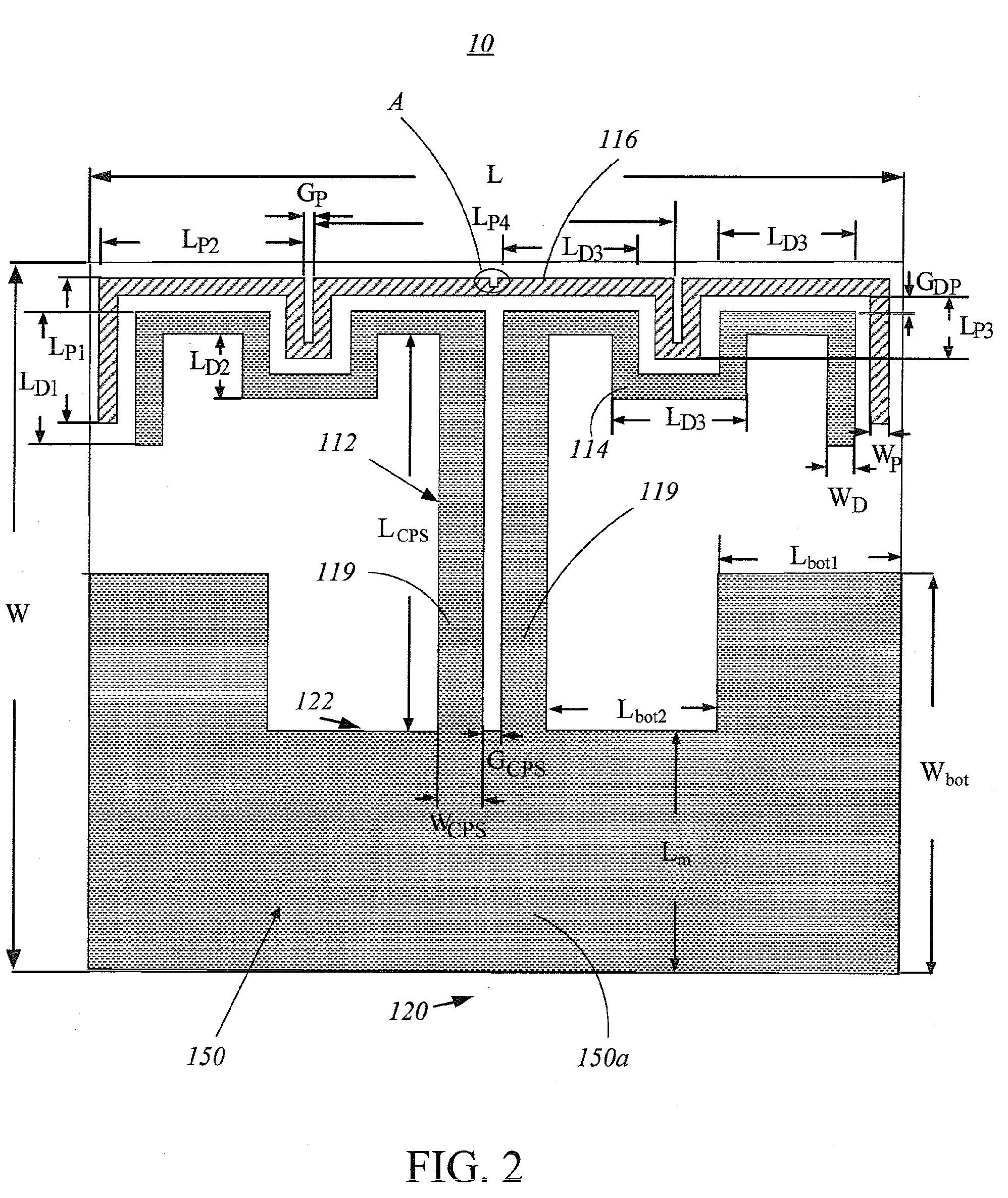
[0018]Please refer to FIGS. 1, 2 and 3. FIG. 1 shows a first plane of an Ultra High Frequency (UHF) radio frequency planar antenna 10 according to a first embodiment of the present invention, FIG. 2 shows a second plane of the ultra high frequency radio frequency plane antenna 10 according to a first embodiment of the present invention, and FIG. 3 depicts an enlarged diagram of area A shown in FIG. 1. The planar antenna 10 is designed for UHF RFID applications in North America, i.e. in the frequency range of 902-928 MHz. In this embodiment, the planar antenna 10 with a width W of 90 millimeter (mm) and a length L of 90 mm, comprises a first plane 110 and a second plane 120. The first plane 110 comprises a part of truncated ground plane 150, a balun 112, a driven dipole 114 and a parasitic element 116. The truncated ground plane 150 comprises a first truncated ground plane 150a on the second plane 120, and a second and a third truncated ground planes 150b, 150c on the first plane 110...


PUM


Abstract

An ultra high frequency antenna includes a first plane, a second plane opposite to the first plane by a distance, a driven dipole, at least a parasitic element having an indentation, and a balun. The balun includes a coplanar strip line and a microstrip line which has a first strip, a second strip area parallel to the first strip, and a third strip perpendicular to the first and second strips. The coplanar strip line coupled to a truncated ground plane with two narrow slots. The present planer antenna features a compact size, wide impedance bandwidth, moderate gain, and excellent front-to-back ratio. This antenna is well suitable for the applications in RFID handheld readers.

Description

RELATED APPLICATIONS[0001]This application claims the priority of Taiwan Patent Application No. 097120197, filed on May 30, 2008. This invention is partly disclosed in a published article, Ren-Chi Hua, and Tzyh-Ghuang Ma, “A Printed Dipole Antenna for Ultra High Frequency (UHF) Radio Frequency Identification (RFID) Handheld Reader,” IEEE TRANSACTIONS ON ANTENNAS AND PROPAGATION, VOL. 55, NO. 12, DECEMBER 2007BACKGROUND OF THE INVENTION[0002]1. Field of the Invention[0003]The present invention relates to an ultra high frequency planer antenna, more particularly, to an ultra high frequency planer antenna for ultra-high-frequency (UHF) radio frequency identification (RFID) systems.[0004]2. Description of the Related Art[0005]In recent years, ultra-high-frequency radio frequency identification systems have drawn more and more attentions in a wide variety of applications such as automatic retail item management, warehouse management, access control system, electronic toll collection, and...

Claims


Application Information

Patent Timeline
IPC IPC(8): H01Q9/16
CPCH01Q1/2225H01Q19/30H01Q9/285H01Q9/26
Inventor MA, TZYH-GHUANGHUA, REN-CHINGTSAI, JYH-WOEI
Owner NAT TAIWAN UNIV OF SCI & TECH
Why Eureka
Try Eureka