Package For Light-Emitting Device, Light-Emitting Apparatus, and Illuminating Apparatus
- Summary
- Abstract
- Description
- Claims
- Application Information
AI Technical Summary
Benefits of technology
Problems solved by technology
Method used
Image

Examples
first embodiment
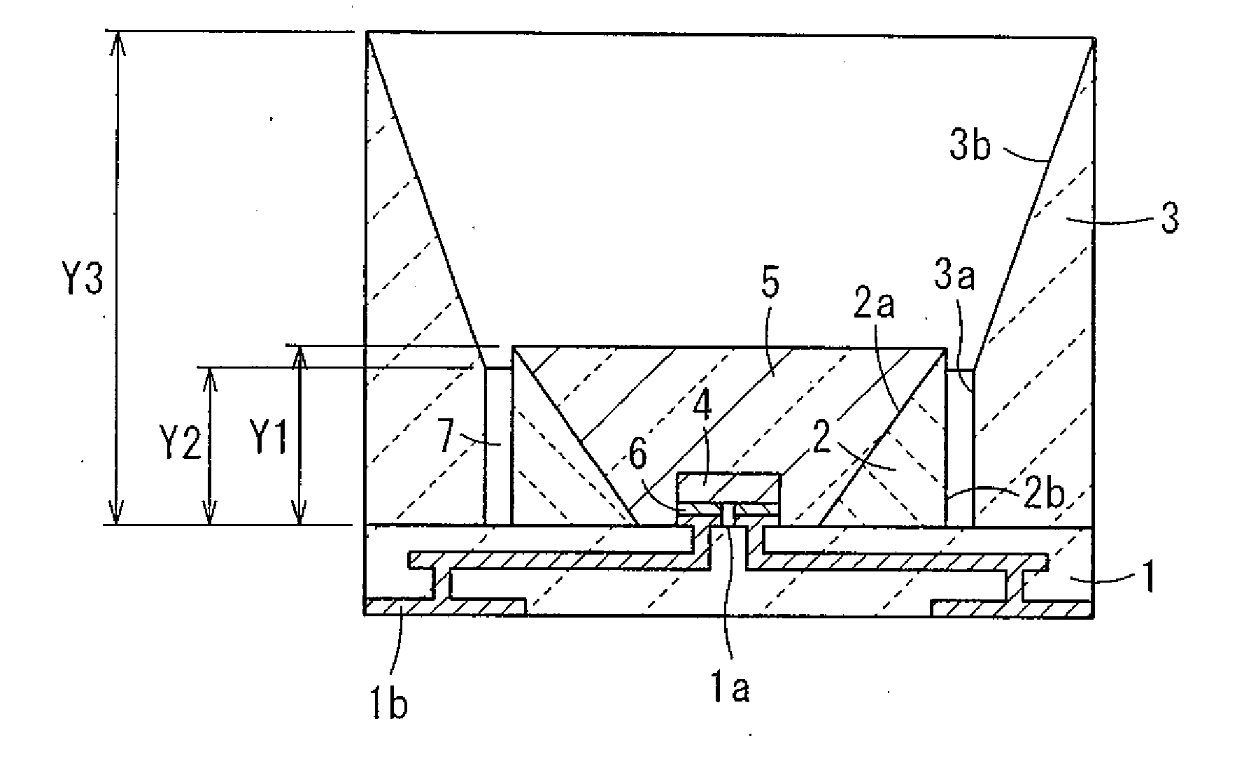
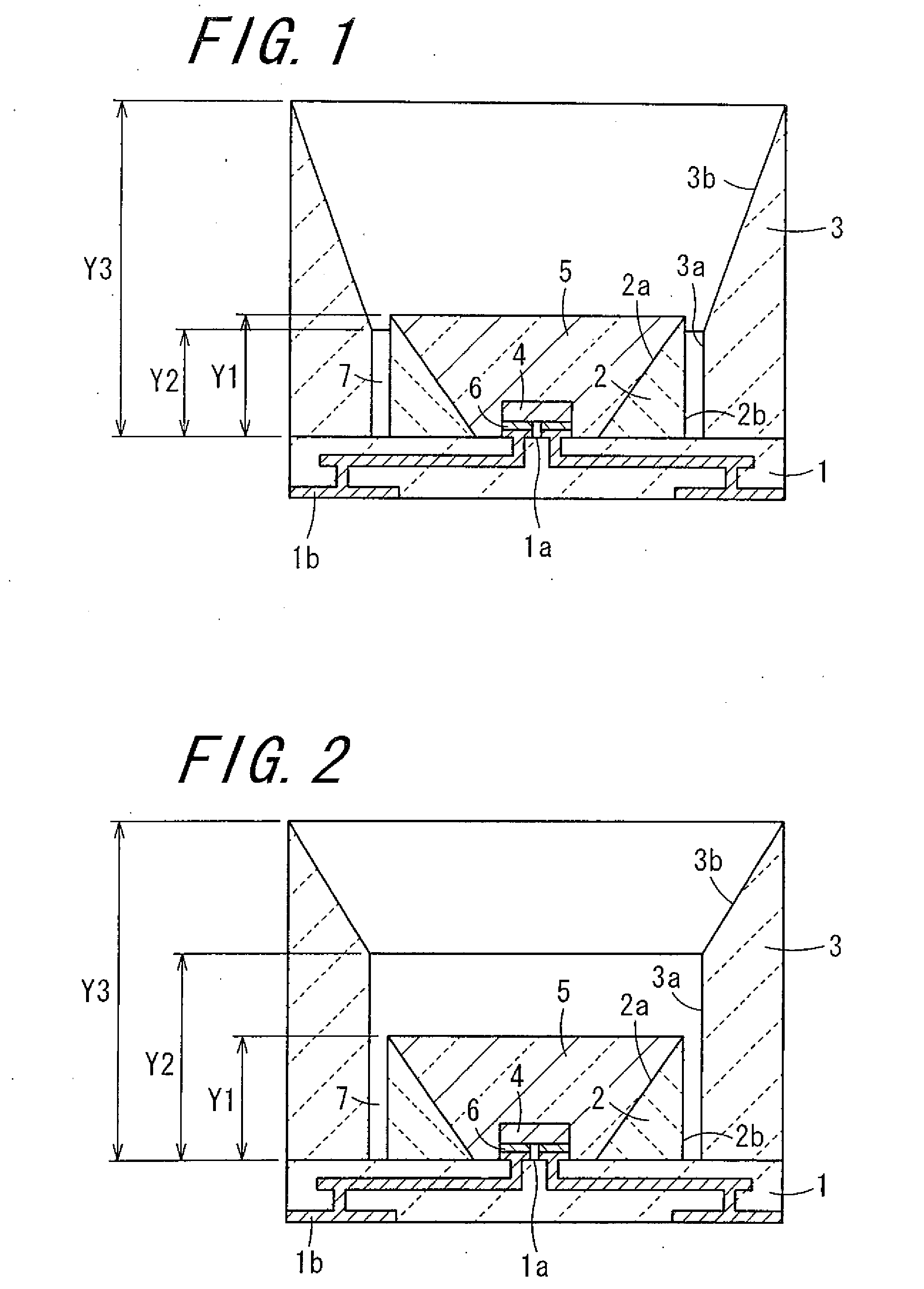
[0043]Now, a detailed description will be given below as to a package for a light-emitting device and a light-emitting apparatus employing the same, and an illuminating apparatus according to the invention. FIG. 1 is a sectional view showing the light-emitting apparatus in accordance with the invention. In this figure, the package for a light-emitting device is constructed mainly of a base body 1, a first reflection member 2, and a second reflection member 3. Moreover, the light-emitting apparatus for housing therein a light-emitting device 4 is constructed by disposing mainly the light-emitting device 4 and a light-transmittable member 5 in the package of the invention. The light-transmittable member 5 is disposed inside the first reflection member 2 so as to cover the light-emitting device 4.
[0044]The base body 1 is made of a ceramic material such as sintered aluminum oxide (alumina ceramics), sintered aluminum nitride, and glass ceramics, or a resin material. In the center of the...
fourth embodiment
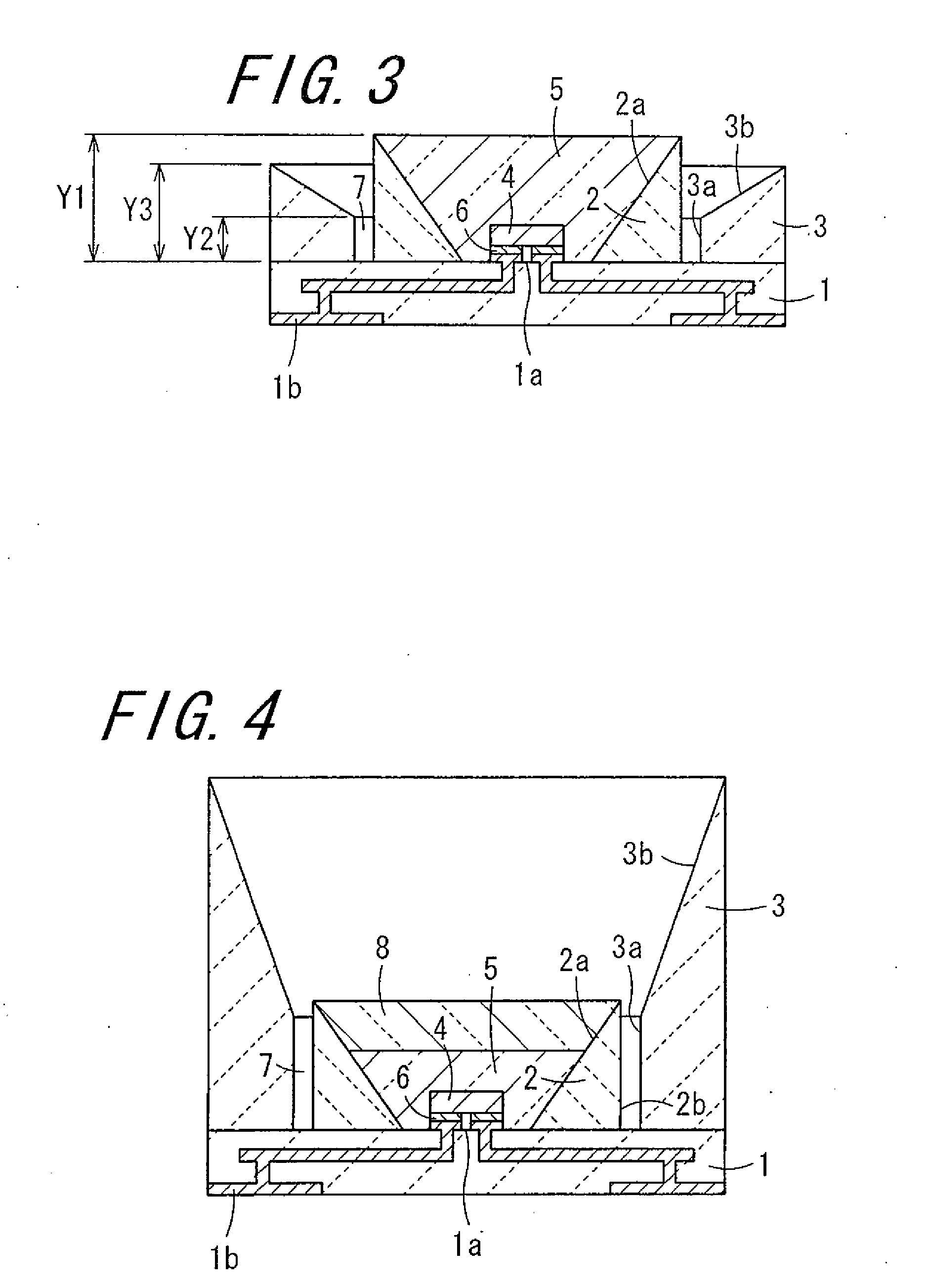
[0078]Moreover, as seen in FIG. 4 showing the invention, the light-transmittable member 5 may take on another structure; that is, the transparent light-transmittable member 5 is arranged inside the first reflection member 2, and a sheet-like layer 8 made of a transparent member containing a fluorescent substances is so arranged as to cover the upper surface of the light-transmittable member 5. In this case, in the absence of the fluorescent substances around the light-emitting device 4, it is possible to suppress confinement of light by the fluorescent substances, and thereby prevent occurrence of quality degradation in the resin material around the light-emitting device 4 and absorption loss of light. As a result, light can be produced through the light-emitting device 4 with high efficiency and the sheet-like phosphor layer 8 is irradiated with the light. Therefore, the optical power level of the light emitted from the fluorescent substances is raised, and it is possible to manufa...
fifth embodiment
[0079]Moreover, by way of the invention, as seen in FIG. 5A which is a sectional view of the embodiment and FIG. 5B which is a perspective view, partly in section, of the embodiment, it is preferable that the light-emitting apparatus is composed of the aforestated package, the light-emitting device 4 mounted on the mounting portion 1a, and the fluorescent substances layer 8 attached to the second reflection member 3 so as to stop up the opening portion of the second reflection member 3. The light emitted from the light-emitting device 4 is partly or wholly converted to the desired wavelength by the fluorescent substances layer 8. In this construction, it is possible to prevent deterioration in the characteristics of the fluorescent substances layer 8 which is ascribable to the heat liberated by the light-emitting device 4. That is, in the case of arranging the fluorescent substances layer 8 in the opening portion of the second reflection member 3, as compared with the case of arrang...
PUM
 Abstract
Description
Claims
Application Information
 - R&D
- Intellectual Property
- Life Sciences
- Materials
- Tech Scout
- Unparalleled Data Quality
- Higher Quality Content
- 60% Fewer Hallucinations
Browse by: Latest US Patents, China's latest patents, Technical Efficacy Thesaurus, Application Domain, Technology Topic, Popular Technical Reports.
© 2025 PatSnap. All rights reserved.Legal|Privacy policy|Modern Slavery Act Transparency Statement|Sitemap|About US| Contact US: help@patsnap.com