Connection Structure For Different Kinds of Metal Tubes

a technology of connecting structure and metal tube, which is applied in the direction of hose connection, sleeve/socket joint, mechanical apparatus, etc., can solve the problems of difficult to change the material from aluminum to stainless steel, difficult to achieve a reliable joint with high strength and high hermeticity, and large connection structure. , the effect of excellent strength and hermeticity

Inactive Publication Date: 2008-08-21
NICHIRIN CO LTD
View PDF6 Cites 14 Cited by
  • Summary
  • Abstract
  • Description
  • Claims
  • Application Information

AI Technical Summary

Benefits of technology

[0026]The present invention provides a small connection structure, having excellent strength and hermeticity, for dissimilar metal tubes by a relatively easy technique. The present invention facilitates the application of a connection structure for connecting dissimilar metal tubes, i.e., a connection structure for connecting a stainless-steel bellows tube to an aluminum alloy tube, to CO2 refrigerant circuit of an automotive air conditioner, thereby striking a balance between reductions in global environmental impact and the weight of an automotive body.

Problems solved by technology

Aluminum alloy pipes have recently been used in the piping of refrigerant circuits of automotive air conditioners to reduce the weight of automotive bodies; however, vibration in the compressor or the like may cause the piping to resonate, resulting in noise generation.
However, when the vibration-absorbing hose is incorporated in the refrigerant circuit, the following problems arise: in the present circumstances, the bellows of the vibration-absorbing hose must be composed of stainless steel in view of processability and strength.
On the other hand, the refrigerant circuit piping needs to be composed of aluminum (or an aluminum alloy) in view of a reduction in the weight of an automotive body and costs; hence, it is difficult to change the material from aluminum to stainless steel.
However, it is significantly difficult to achieve a reliable joint with high strength and high hermeticity by only mechanically fitting or screwing these metal pipes.
Furthermore, joining aluminum with stainless-steel by welding or brazing easily forms a brittle intermetallic compound in the joint; hence, also in this case, it is significantly difficult to achieve a reliable joint with high strength and high hermeticity.
This disadvantageously increases production and material costs.

Method used


Image

  • Connection Structure For Different Kinds of Metal Tubes
  • Connection Structure For Different Kinds of Metal Tubes
  • Connection Structure For Different Kinds of Metal Tubes

Examples


Embodiment Construction

[0051]Embodiments of the present invention will be described in detail below with reference to the attached drawings.

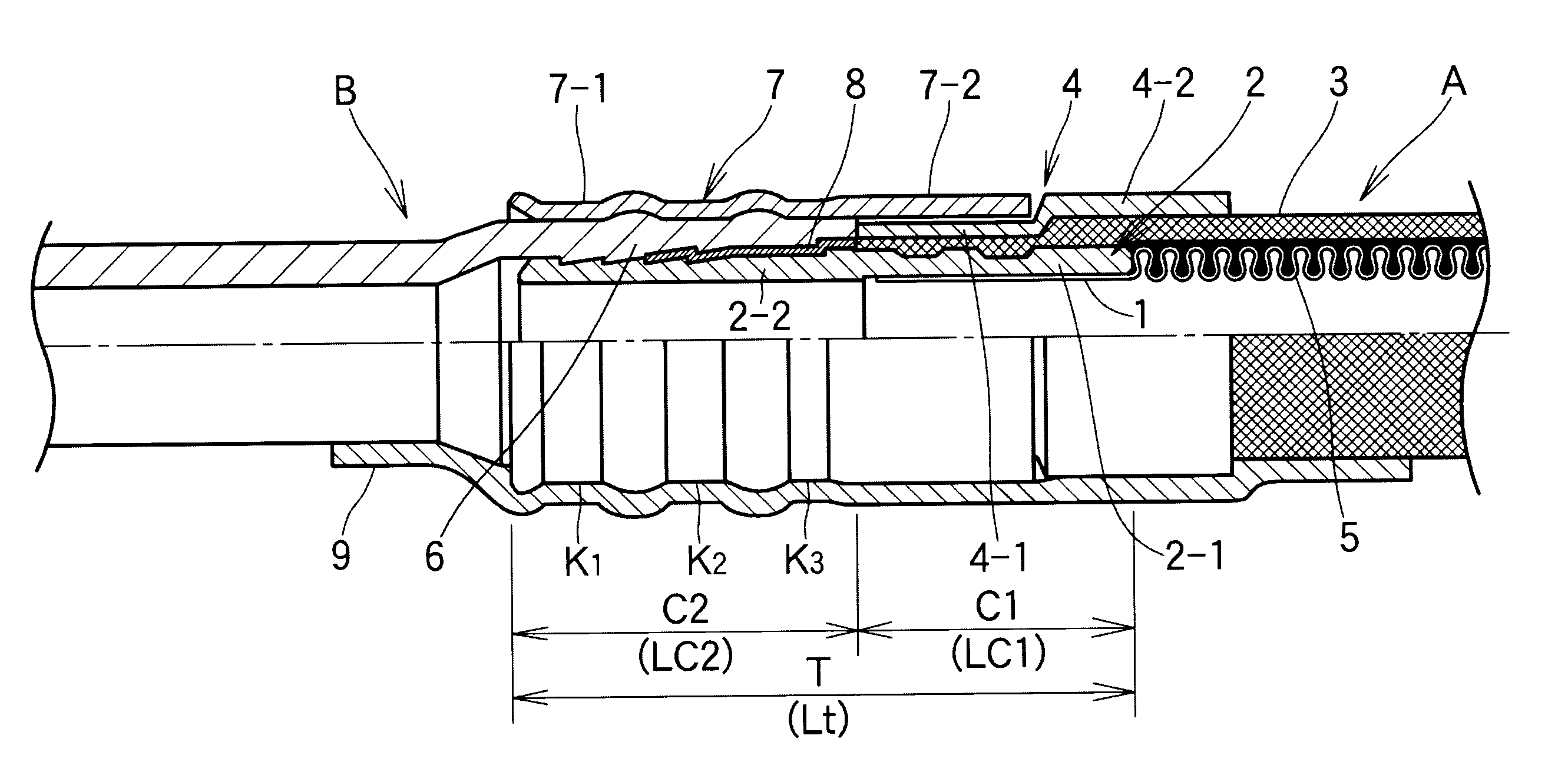
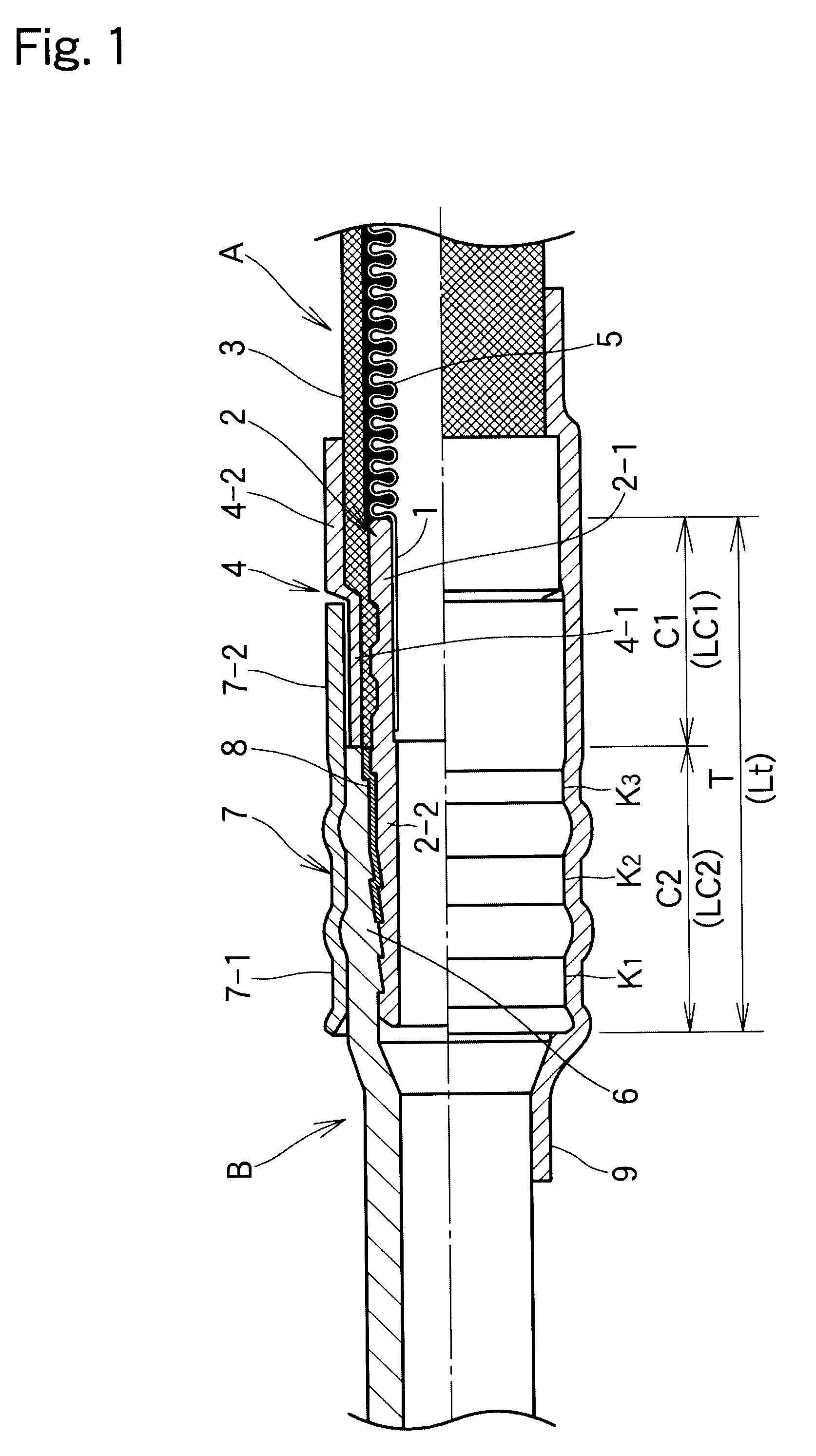
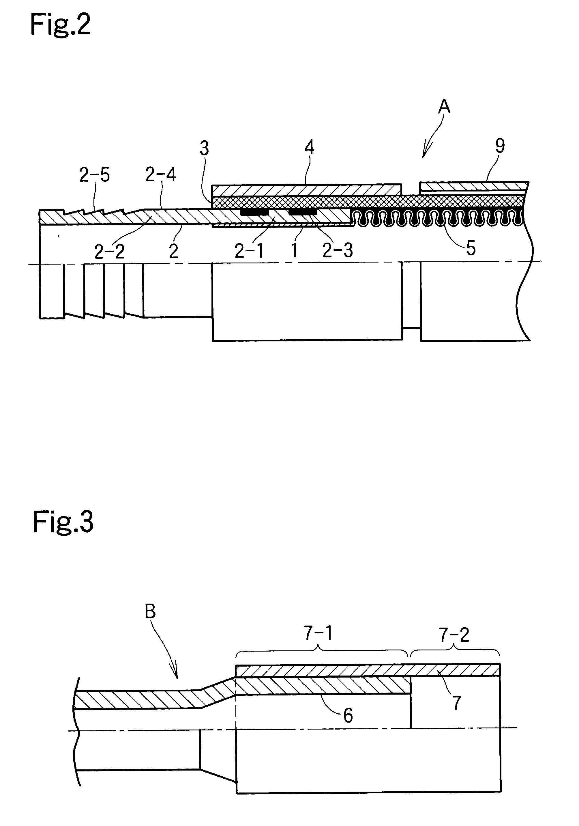
[0052]FIG. 1 shows a typical embodiment of the present invention and shows a preferred connection structure in which a metal bellows tube composed of stainless steel (hereinafter, also referred to as a “stainless-steel bellows tube” or “bellows tube”) serving as a vibration-absorbing tube is connected to a metal tube composed of an aluminum alloy (hereinafter, also referred to as a “aluminum tube”) serving as a circuit piping in the middle of a CO2 refrigerant circuit for use in an automotive air conditioner. FIGS. 2 and 3 show connection parts of individual pipes before connection. FIG. 2 shows the stainless-steel bellows tube side. FIG. 3 shows the aluminum tube side.

[0053]The structure of the present invention will now be described in detail on the basis of FIGS. 2 and 3 including a process of forming the final connection structure shown in FIG. 1.

[0054]As shown in...


PUM

PropertyMeasurementUnit
pressureaaaaaaaaaa
temperatureaaaaaaaaaa
pressureaaaaaaaaaa

Abstract

A connection structure for connecting dissimilar metal tubes includes a metal bellows tube (A) having a reinforcement portion (3) disposed on the outer surface of the bellows (5), and a metal tube (B) composed of a material different from that of the bellows tube, the metal bellows tube (A) being integrally connected to the metal tube (B). A connection section on the bellows tube side includes a straight tube portion (1) of the bellows tube (A), a nipple (2), the reinforcement portion (3), and a crimp collar (4), being fitted and secured to each other in that order from the inside of the tube. The nipple (2) has a base (2-1) joined to the reinforcement portion (3) and a connection end (2-2) extending to the metal tube (B) side farther than an end face of the crimp collar (4). The crimp collar (4) has a small-diameter portion (4-1) located on the metal tube (B) side and a large-diameter portion (4-2) located on the bellows side of the metal bellows tube, the small-diameter portion (4-1) being continuous with the large-diameter portion (4-2). A connection section on the metal tube (B) side includes a connection end (6) of the metal tube (B) and a sleeve (7) secured to the outer side of the connection end (6). The sleeve (7) has a base (7-1) joined to the connection end (6) and a fitting end (7-2) extending to the metal bellows tube (A) side. The fitting end (7-2) of the sleeve (7) on the metal tube (B) side is externally fitted on the small-diameter portion (4-1) of the crimp collar (4) on the metal bellows tube (A) side. The outer surface of the connection end (2-2) of the nipple (2) is bonded and fixed to the inner surface of the connection end (6) of the metal tube (B) with a thermosetting resin while an end face of the reinforcement portion (3) of the metal bellows tube (A) and the end face of the crimp collar (4) are in contact with or close to the end face of the connection end (6) of the metal tube (B).

Description

TECHNICAL FIELD[0001]The present invention relates to connection structures for connecting dissimilar metal tubes. In particular, the present invention relates to a connection structure for connecting a vibration-absorbing hose used for the refrigerant circuit of an automotive air conditioner to the piping of the circuit.BACKGROUND ART[0002]Aluminum alloy pipes have recently been used in the piping of refrigerant circuits of automotive air conditioners to reduce the weight of automotive bodies; however, vibration in the compressor or the like may cause the piping to resonate, resulting in noise generation. In order to damp the piping resonance, composite hoses formed of multiple layers of rubber and resin have thus been incorporated in the middle of the piping.[0003]In the meanwhile, HFC134a has been used in place of chlorofluorocarbons, which are ozone-destroying substances, as a refrigerant for automotive air conditioners. HFC134a has zero ozone depletion potential but has high gl...

Claims


Application Information

Patent Timeline
Patent Type & Authority Applications(United States)
IPC IPC(8): F16L51/02F16L21/00
CPCF16L13/103F16L47/24F16L33/34F16L25/0072F16L13/10F16L33/26
Inventor NAKANO, YOSHIOKATAYAMA, TOSHIYUKIYAGI, TAKASHIMATSUI, MASAMICHI
Owner NICHIRIN CO LTD
Why Eureka
Try Eureka