
Devices and Methods for Resonant Illumination

a technology of resonant illumination and devices, applied in semiconductor devices, lighting and heating apparatus, instruments, etc., can solve problems such as significant problems, reduced illumination coverage area, and undesirable use of large-power traditional light bulbs

Inactive Publication Date: 2009-12-03
OMNILUX
View PDF22 Cites 10 Cited by
  • Summary
  • Abstract
  • Description
  • Claims
  • Application Information

AI Technical Summary

Benefits of technology

[0019]Additional features may also be included to the devices and systems described herein. In particular, a light source may be used. Any appropriate light source may be used, including light sources selected from the group consisting of: a florescent bulb, an incandescent bulb, an LED, a halogen bulb, a flash lamp, a coherent light source (e.g., a laser), an IR lamp, a UV lamp, an optical cable, and a solar light source. Collimated or concentrated light is particularly useful, because it may be accurately directed by the mirror(s) of the resonant engine. Thus, a light source may include one or more collimating or concentrating elements (e.g., mirrors, lenses, reflectors, etc.). The light source may be attached to the engine support (e.g., housing) of the device, or it may be separate. For example, a light source may be separably positionable from the mirror-containing resonant engines (devices) described herein. Multiple light sources may be used with the same resonant engine. This may also permit the resonant engines described herein to be versatile, and adapted for use with a variety of light sources. Further, a single variation of a resonant engine may be simultaneously with different light sources. In some variations, a light source is integral to the device having the oscillating mirror(s). In some variations, an illumination device includes a mount for positioning the illumination device.
[0021]Also described herein are methods for efficiently illuminating a wide pattern of illumination. For example, one variation of a method for efficiently illumination a wide pattern of illumination includes illuminating a light source, and moving a movable mirror at a resonant frequency to project light from the light source into a wide pattern of illumination. The resonant frequency is between about 10 and about 1000 Hz (e.g., in some variations, the resonant frequency is between about 40 and about 120 Hz).
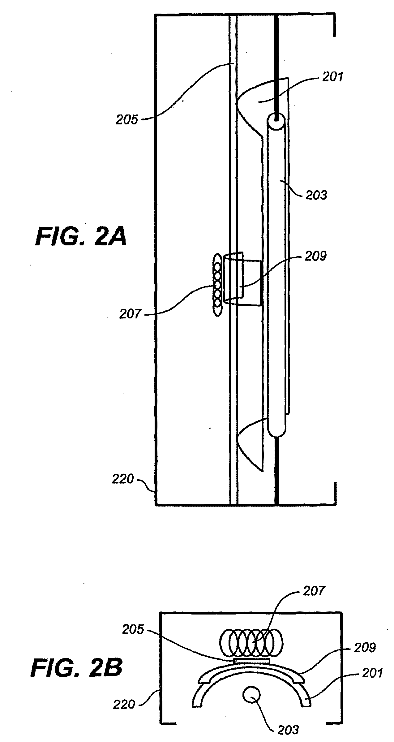
[0028]The devices described herein may also have a cover for the engine support, particularly when it is configured as a housing. At least a portion of the mirror may be positioned outside of the region enclosed by the cover and housing. The housing and cover may enclose and protect the bias, and at least a portion of the rotor. The rotor may project out of the housing and include a mounting region for attaching or securing the mirror.
[0029]In some variations, the devices and systems described herein include one or more control circuits (or control circuitry) for controlling the energy applied to the stator to act on the rotor. For example, printed circuit board (PCB) may be included (e.g., within the housing). The control circuitry may be connected to one or more sensors. Thus, any of the devices and systems described herein may include one or more sensors. Sensors may monitor the motion of the mirror (and or the rotor), and may help control the oscillation of the mirror (or subassembly). For example, the sensor(s) may provide feedback to the control circuit. The control circuit may help operate the device so that the mirror oscillates at or near a resonant frequency.
[0033]These devices and systems described herein may provide continuous illumination of a wide area, due in part to the characteristics of the human eye. Psychotropic properties of the human visual system make it unable to detect light motion beyond a certain frequency. Thus, movement of a light source may yield the perception of continuous light, or of a higher perceived intensity of light, or other effect.

Problems solved by technology

The resulting illumination area typically radiates from the illumination source (e.g., bulb), and may be non-uniform.
Focused lamp devices typically increase brightness but decrease illumination coverage area.
The use of larger power traditional light bulbs is therefore undesirable.
However, significant problems arise when scanning a light source over a large area (which may also be referred to as a moving lamp design).
For example, moving a lamp at a non-resonant frequency typically requires increased power and / or increased cost.
Additionally moving the lamp device may decreases the reliability and operating life of the bulb due to mechanical shock and stress.
Unfortunately, few common bulbs hold up well under the forces created by this mechanical movement.
Common bulbs are typically composed of glass and metal both of which are relatively heavy, requiring an increase in energy required to provide movement.
One undesirable side-effect of oscillating the beam of light is the stroboscopic effect (including temporal aliasing).
However, increasing the rate of movement typically requires increasing the energy needed to move the light source, and may further degrade the illumination system components, as increased stresses may be applied to the system.
The system may illuminate a broad (or adjustable) area by efficiently oscillating one or more mirrors at or near a resonant frequency in a relatively undamped manner, resulting in a rapid oscillation that requires only minimal energy to sustain.

Method used


Image

  • Devices and Methods for Resonant Illumination
  • Devices and Methods for Resonant Illumination
  • Devices and Methods for Resonant Illumination

Examples


Embodiment Construction

[0066]Described herein are devices, systems and methods for providing area illumination by resonant oscillation of one or more mirrors. Such devices, systems and methods may offer enhanced illumination with minimal power consumption. These devices may be referred to as “resonant engines,”“resonant lighting,” or “resonant engines for adjustable light.” Thus the systems may be referred to as “R.E.A.L” systems (“resonant engines for adjustable light” systems) or resonant engine systems.

[0067]In general, the devices described herein include a mirror (or multiple mirrors) that is mounted to a bias. The mirror and bias may form a mirror subassembly that is attached to an engine support (e.g., housing). The mirror subassembly may include additional components (e.g., a rotor or other portion of the mirror driver), and is typically mounted so that it may be moved (e.g., oscillated) in a substantially undamped fashion continuously at or near the resonant frequency of the mirror subassembly. T...


PUM


Abstract

Described herein are methods, devices and systems for effective, adjustable wide-field illumination. In particular resonant engines for illuminating a broad area by resonant oscillation, and methods of moving at least one mirror at or near a resonance are described. A resonant engine includes one or more mirrors that may be oscillated to reflect light from a light source(s) to create a target illumination pattern. Devices and systems in which the mirror or mirrors are oscillated at an energy-efficient manner are described. Also described are optics, control features, and techniques that may be utilized to enhance the energy efficiency of the resonant engines and system described.

Description

CROSS-REFERENCES TO RELATED INVENTIONS[0001]This patent claims priority to U.S. Provisional Patent application 60 / 784,435, filed Mar. 20, 2006, which is herein incorporated by reference in its entirety.TECHNICAL FIELD[0002]This application generally relates to the field of illumination and light devices. In particular, the application relates to uniform and adjustable illumination of a wide area. The application applies both to visible and non-visible regions of the electromagnetic spectrum.BACKGROUND[0003]Most lighting devices are static lighting devices. This means that these lighting devices operate by providing an illumination source (e.g., a lamp) that emits light in a fixed or stationary pattern. Power is provided to the lamp, and the light emitted may be at least partially reflected by a mirror to illuminate a target or target region. Static lighting devices may include handheld, mobile and fixed mount lighting. One example of a static lighting device is an interior residenti...

Claims


Application Information

Patent Timeline
Patent Type & Authority Applications(United States)
IPC IPC(8): F21V17/02
CPCF21V14/04F21Y2103/003F21Y2101/02G02B27/30G02B26/0816F21Y2103/10F21Y2115/10
Inventor GUTIERREZ, JR., ENRIQUE
Owner OMNILUX
Learn More